Need help to understand how to set ResliceAxes for imageReslice

I had a hard time to use imageReslice. Basically the only thing required here is ResliceAxes. I checked the instruction but doesn’t seem to work well for me. so I checked the source code vtk.js\Sources\Widgets\Widgets3D\ResliceCursorWidget\index.js, could someone help me to understand section 6 of the code, especially the code

vec4.transformMat4(originXYZW, planeOrigin, newResliceAxes);
mat4.transpose(newResliceAxes, newResliceAxes);
vec4.transformMat4(newOriginXYZW, originXYZW, newResliceAxes);

why planeOrigin needs to be transformed by newResliceAxes? isn’t the planeSource alreay transformed and bounded? why newOriginXYZW needs to be computed this way? why newResliceAxes needs to be transposed? what’s the correct way to set ResliceAxes? does it matter to use [p1-o, p2-o,normal, center] or [p2-o, p1-o,-normal, center] ?

Thanks!

publicAPI.updateReslicePlane = function (imageReslice, viewType) {
// 1. Calculate appropriate pixel spacing for the reslicing
var spacing = model.widgetState.getImage().getSpacing();
// 2. Compute original (i.e. before rotation) plane (i.e. origin, p1, p2) centered on cursor center.
var planeSource = computeReslicePlaneOrigin(viewType);
var _model$widgetState$ge = model.widgetState.getPlanes()[viewType], normal = _model$widgetState$ge.normal, viewUp = _model$widgetState$ge.viewUp;
// 3. transform planeSource to fit the correct normal, viewUp and center
transformPlane(planeSource, model.widgetState.getCenter(), normal, viewUp); // Clip to bounds
// 4. bound plane so o,p1,p2 are image bounded
var boundedOrigin = _toConsumableArray(planeSource.getOrigin());
var boundedP1 = _toConsumableArray(planeSource.getPoint1());
var boundedP2 = _toConsumableArray(planeSource.getPoint2());
boundPlane(model.widgetState.getImage().getBounds(), boundedOrigin, boundedP1, boundedP2);
planeSource.setOrigin.apply(planeSource, _toConsumableArray(boundedOrigin));
planeSource.setPoint1.apply(planeSource, _toConsumableArray(boundedP1));
planeSource.setPoint2.apply(planeSource, _toConsumableArray(boundedP2));
var o = planeSource.getOrigin();
var p1 = planeSource.getPoint1();
var p2 = planeSource.getPoint2();
// 5. compute plane size and spacing
var planeAxis1 = ;
subtract(p1, o, planeAxis1);
var planeAxis2 = ;
subtract(p2, o, planeAxis2); // The x,y dimensions of the plane
var planeSizeX = normalize(planeAxis1);
var planeSizeY = normalize(planeAxis2);
var spacingX = Math.abs(planeAxis1[0] * spacing[0]) + Math.abs(planeAxis1[1] * spacing[1]) + Math.abs(planeAxis1[2] * spacing[2]);
var spacingY = Math.abs(planeAxis2[0] * spacing[0]) + Math.abs(planeAxis2[1] * spacing[1]) + Math.abs(planeAxis2[2] * spacing[2]);
// 6. set newResliceAxes
var newResliceAxes = mat4.identity(new Float64Array(16));
for (var i = 0; i < 3; i++) {
newResliceAxes[4 * i + 0] = planeAxis1[i];
newResliceAxes[4 * i + 1] = planeAxis2[i];
newResliceAxes[4 * i + 2] = normal[i];
}
var planeOrigin = [o[0],o[1],o[2],1.0]);
var originXYZW = ;
var newOriginXYZW = ;
vec4.transformMat4(originXYZW, planeOrigin, newResliceAxes);
mat4.transpose(newResliceAxes, newResliceAxes);
vec4.transformMat4(newOriginXYZW, originXYZW, newResliceAxes);
newResliceAxes[4 * 3 + 0] = newOriginXYZW[0];
newResliceAxes[4 * 3 + 1] = newOriginXYZW[1];
newResliceAxes[4 * 3 + 2] = newOriginXYZW[2];
var modified = imageReslice.setResliceAxes(newResliceAxes);
// Compute a new set of resliced extents
This code is coming from vtkResliceCursorRepresentation.cxx.

My understanding is that the translation component of the matrix must be expressed in the “resliced” matrix orientation.

Thanks, Julien.

I understand that imageReslice needs to call setResliceAxes(newResliceAxes) to set it up.

“The first column of the matrix specifies the x-axis
vector (the fourth element must be set to zero), the second
column specifies the y-axis, and the third column the
z-axis. The fourth column is the origin of the
axes (the fourth element must be set to one).”

if you examine the code,

  1. planeSource is created on the fly, it has nothing to do with imageReslice, and it’s whole purpose is to get bounded [o, p1, p2] points according to the specified [center, normal, viewUp) in widgetState, here center is the point on which the three planes share/cross.
  2. so once the bounded o1 is obtained, newResliceAxes can be simply set as

var newResliceAxes = mat4.identity(new Float64Array(16));
for (var i = 0; i < 3; i++) {
newResliceAxes[4 * i + 0] = planeAxis1[i];
newResliceAxes[4 * i + 1] = planeAxis2[i];
newResliceAxes[4 * i + 2] = normal[i];
newResliceAxes[4 * i + 3] = o[i];
}

apparently this is not the case here checking section 6. So exactly how “newResliceAxes” needs to be setup? ImageReslice is an extremely useful class but the documentation is also very hard to grasp and no much example to demonstrate its usage…

So exactly how “newResliceAxes” needs to be setup?

@dgobbi may have an answer for you.

[…] but doesn’t seem to work well for me

Can you please explain what problem you are facing in the first place ?

FYI, and if that helps, I recently contributed a PR that adds support for “oriented” image and custom image transform.

I’m unfamiliar with the ResliceCursorWidget code, so I might be wrong, but here is my interpretation of this code:

vec4.transformMat4(originXYZW, planeOrigin, newResliceAxes);
mat4.transpose(newResliceAxes, newResliceAxes);
vec4.transformMat4(newOriginXYZW, originXYZW, newResliceAxes);

The transpose() is only needed because the rows of the matrix were set to planeAxis1, planeAxis2, and normal. If the columns were set instead, the transpose would not be necessary.

For an orthonormal matrix, the transpose is mathematically identical the inverse, and newOriginXYZW will be identical to planeOrigin. So that part of the code doesn’t make sense to me,

1 Like

Apologies, I thought you were the original author, but it was @Karthik_Krishnan .

Thanks for your insights though. I just simplified the code in this PR.

Thanks David and Julien. Indeed the matrix can be simply set with column major of axis1,axis2,and normal.

so it seems to be working, but I have an even more difficult problem now as how to control the size of the slice.

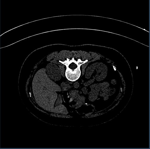
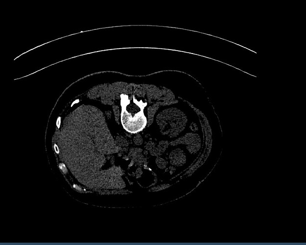
the first picture is what starts normally, however, once I rotate it generates additional blank space on both left and right, and the right side is more obvious to see.

My question is, what is causing this and how to avoid and limit the slice within the bounds of the original image object.

I see member functions like setOutputSpacing, setOutputExtent, setOutputOrigin, I am not sure if it is related, and also, because I do not understand these functions the code will freeze if I try to use any of these functions. So please help. Thanks!

In general, an image data set is defined by two things:

  1. the positions of the samples
  2. the values of the samples

I use the word “samples” instead of “voxels” because it’s a more general (and more useful) term.

For VTK images, the Origin, Extent, and Spacing (and Direction, if present) specify the positions of the samples. The scalars specify the values of the samples.

Note that the Origin of the vtkImageData is not the Origin of the plane. They have the same name, but they are not the same thing!

The OutputOrigin will be transformed by the ResliceAxes to give the corresponding point in the input data. So you probably want to set the OutputOrigin to (0,0,0), so that when you multiply it by your ResliceAxes it will give the “Origin” of your vtkPlaneSource.

The OutputSpacing should generally be the same as the spacing of the input data, if the input spacing is isotropic.

The OutputExtent can be computed from the OutputSpacing and the size of the plane.

In order to use my advice, you need to choose the best origin and size of the plane (i.e. the bounds of the plane) according to your needs.

1 Like

Thanks, David. In a slanted position (with a given normal, and three points p0, p1, p2 of the plane which are bounded to the image, and the original spacing(x,y,z) not isotropic), how should I set output spacing and extent? Is outputOrigin default to (0,0,0)? shouldn’t plane origin defaults to p0?

I’ll answer when I can, but please understand that it takes me a lot of time to write good answers to these questions.

So please answer at least this one part of your question by yourself:

What do you think the OutputSpacing should be when the input spacing is not isotropic? And when you answer, explain your reasoning.

Thanks David, seems to be working well now. I used dot projection to get the extent.

Out of curiosity, what did you choose as the OutputSpacing?

it works well, but seems there are some performance issues. I’m double checking it right now to see if it is related.

I use sizeX/extentX to get the spacing. sizeX is determined by [p0, p1, p2], extentX right now I’m using projection as mentioned. still checking if this is soundable.

I think that the easiest way for me to explain how to set up vtkImageReslice for getting an oblique slice from a volume is with some code that I wrote many years ago, in a class called vtkResliceMath (it is old code that I no longer maintain, but it is good for explaining.

This code is not the same as the vtkResliceCursorWidget code. The main difference is that it computes the vtkImageReslice parameters from an unbounded plane, rather than from a bounded plane.

An unbounded plane is described by a point p0 and a normal n, or in simpler form by the four coefficients in this equation:

a*x + b*y + c*z + d = 0

where, using the dot product,

a = n[0], b = n[1], c = n[2]
d = - dot(p0,n)

This C++ code computes the spacing and the physical size of the of the slice plane first, and then uses the size and spacing to compute the extent.

To compute the output spacing from the input spacing, it uses the square of the direction cosines, as shown below. Note that this matrix is a row-major matrix (I think vtk.js uses column-major?)

  // Compute output spacing from input spacing
  spacing[0] = fabs(spacing[0]);
  spacing[1] = fabs(spacing[1]);
  spacing[2] = fabs(spacing[2]);
  double s[2]; // output spacing
  for (int j = 0; j < 2; j++)
  {
    double xc = matrix[4*j + 0];
    double yc = matrix[4*j + 1];
    double zc = matrix[4*j + 2];
    s[j] = (xc*xc*spacing[0] +
            yc*yc*spacing[1] +
            zc*zc*spacing[2])/sqrt(xc*xc + yc*yc + zc*zc);
  }

Note that the division by sqrt(xc*xc + yc*yc + zc*zc) is mostly superflous, because for an orthonormal matrix this will be equal to 1.0 except roundoff error.

The main reason for squaring is because otherwise, when you rotate the plane, there will be certain angles for which the output spacing s[0], s[1], or s[2] will be <= 0.0. Squaring gives better results than just taking the abolute values of the direction cosines.

I compute the physical size of the plane with a similar method, and then use the size and spacing to compute the extent.

  // Compute center, radius from input origin, spacing, and extent
  // (the 'radius' is half of the distance across the image volume)
  double center[4], radius[3];
  for (int i = 0; i < 3; i++)
  {
    center[i] = 0.5*(extent[2*i] + extent[2*i+1]);
    center[i] = center[i]*spacing[i] + origin[i];
    radius[i] = 0.5*(extent[2*i+1] - extent[2*i]);
    radius[i] *= spacing[i];
  }
  center[3] = 1.0;  // homogeneous coordinate

  // Transform the center (invMatrix is inverse of ResliceAxes)
  vtkMatrix4x4::MultiplyPoint(invMatrix, center, center);
  // Compute output 'radius' from input 'radius'
  double r[2];
  for (int j = 0; j < 2; j++)
  {
    double xc = matrix[4*j + 0];
    double yc = matrix[4*j + 1];
    double zc = matrix[4*j + 2];
    r[j] = (xc*xc*radius[0] +
            yc*yc*radius[1] +
            zc*zc*radius[2])/sqrt(xc*xc + yc*yc + zc*zc);
  }

  origin[0] = center[0] - r[0];
  origin[1] = center[1] - r[1];
  origin[2] = 0.0;

  extent[0] = 0;
  extent[1] = int(2*r[0]/s[0]);
  extent[2] = 0;
  extent[3] = int(2*r[1]/s[1]);
  extent[4] = 0;
  extent[5] = 0;

The next step, which isn’t shown in vtkResliceMath.cxx, is to set up the vtkPlaneSource with p0, p1, and p2. We can compute these points in the reslice output coordinate system first, and then use ResliceAxes to transform them to the input coordinate system.

  // origin is the OutputOrigin of vtkImageReslice
  double p0[4] = { origin[0], origin[1], origin[2], 1.0 };
  double p1[4] = { origin[0], origin[1], origin[2], 1.0 };
  double p2[4] = { origin[0], origin[1], origin[2], 1.0 };
  // s is OutputSpacing, and extent is OutputExtent
  p1[0] += s[0]*extent[1];
  p2[1] += s[1]*extent[3];

  // transform to input coordinate system with ResliceAxes
  resliceAxes->MultiplyPoint(p0, p0);
  resliceAxes->MultiplyPoint(p1, p1);
  resliceAxes->MultiplyPoint(p2, p2);

  // now we can use p0, p1, p2 to define our bounded plane

For more image-slicing code, you can look at vtkImageResliceMapper, but that code is much more complicated (there is more than one way to write code to slice an image!). I’m not sure if there is a vtk.js equivalent to vtkImageResliceMapper.

2 Likes

David, thanks for your detailed explanation.