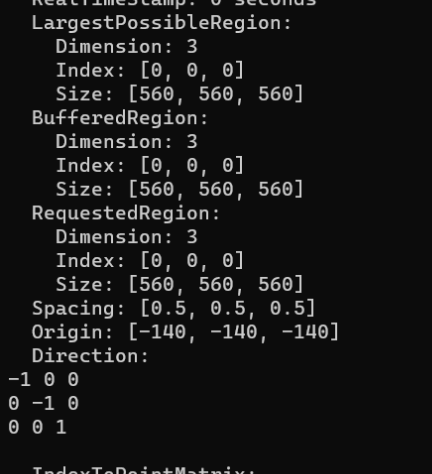
According to the ITK reader, the physical LPS coordinates are in the range:
L [-420, -140] = R 140 to R 420
P [-420, -140] = A 140 to A 420
S [-140, 140] = I 140 to S 140
In Slicer, the G view’s offset (A 297) is in the same range as in ITK, but the yellow view is not (L 285.5). Most likely you have not loaded the image using DICOM module.
If you find the physical coordinates range are still different in ITK and Slicer then please share the image (upload somewhere and post the link here) and I’ll have a look.
WIth both the latest Slicer Stable Release (Slicer-5.2.2) and a recent Slicer Preview Release (Slicer-5.3.0-2023-04-25) the yellow slide range is negative L, which means R, which is correct.