Rendering with priors: MIP and Labelmaps

As I understand the vtk.js rendering pipeline, it renders each volume mapper separately. This is fine for most usecases, but can cause issues, for instance, when you have Maximum Intensity Projection (MIP) and labelmaps, where you want the segmentation to be displayed at the maximum intensity locations.

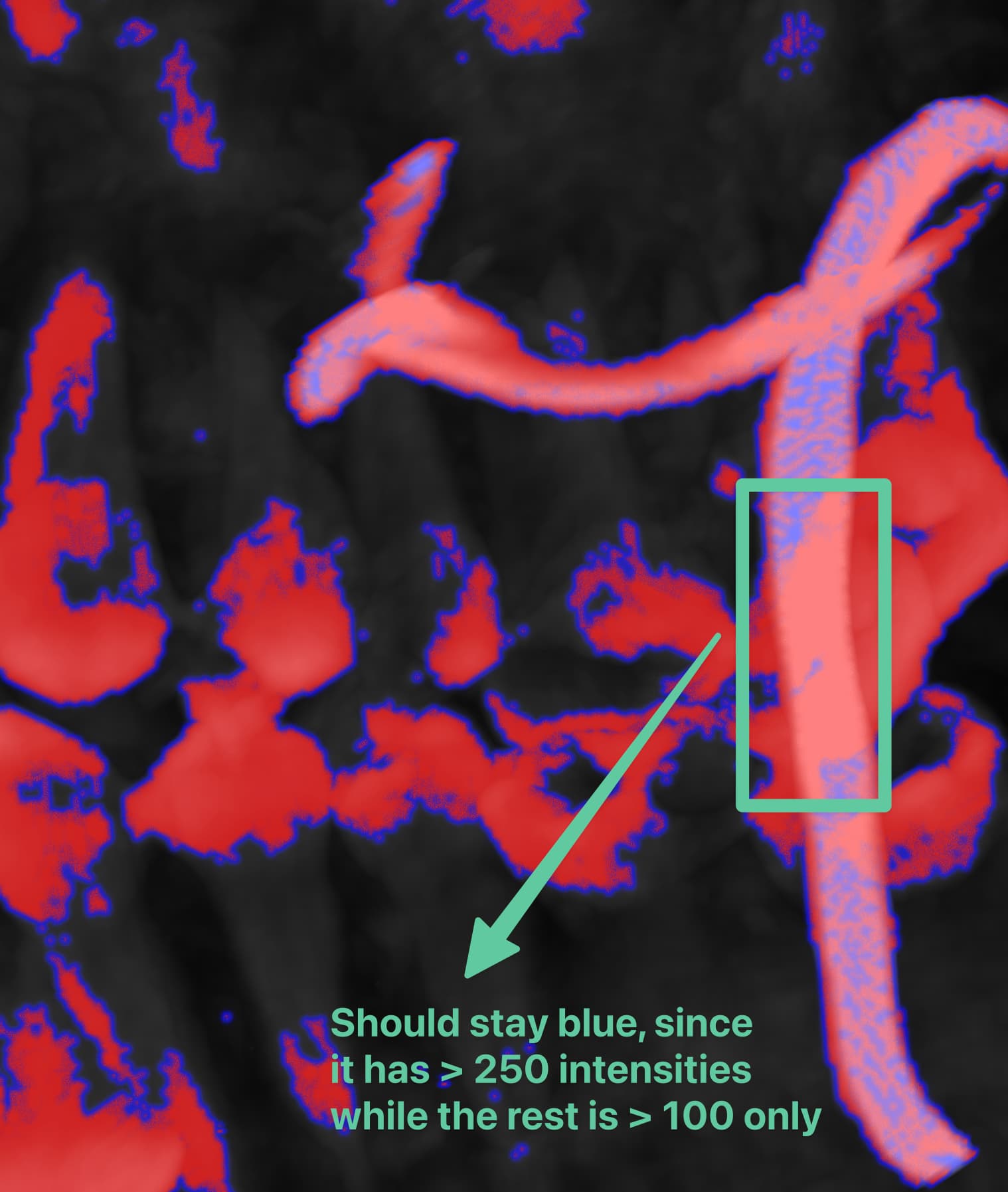
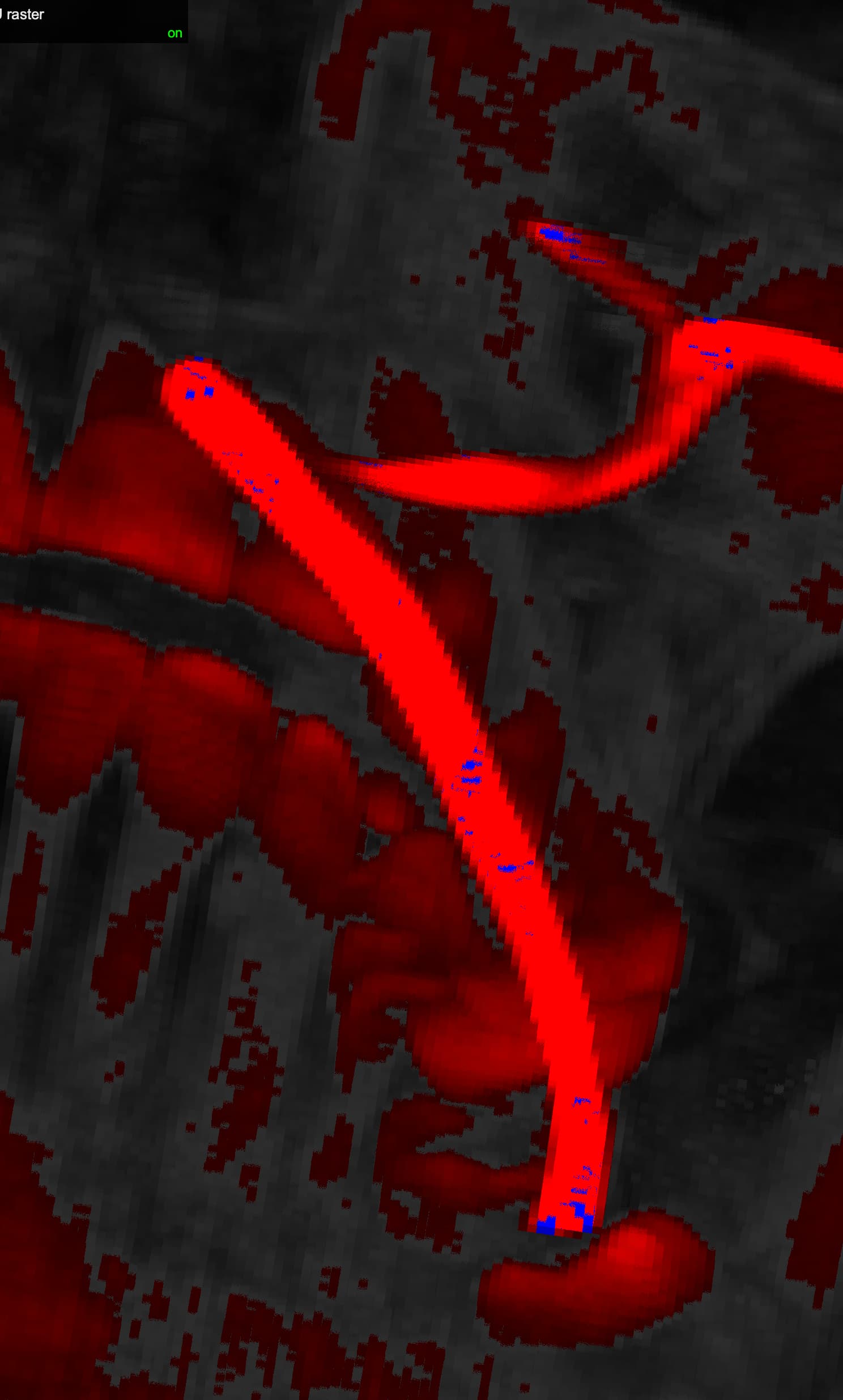
See below for demonstration of what is not ideal

To fix this:

  1. One idea can be to have a super pass (yet to be named) to pass two textures inside gpu, and when the maximum intensity is found, we sample the texture from the labelmap volume instead.

  2. Another idea is to send out the MIP locations after the shader pass to CPU and use that extra information for the labelmap volume pass to sample from the correct locations for each pixel based on the new information of where the maximum intensity is (pass in as another uniform?).

I would like to contribute this feature, and appreciate your thoughts on the pros and cons of each option and determining which one is easier/better to implement.

The ultimate goal is to be able to render an outline for the segmentation over the MIP, but that’s the next step. I need to first get my head around how possible it is to achieve this with regular rendering.

Just briefly, there is now support for custom component blending functionality in the volume mapper. It probably gets close to what you’re looking to do. Here’s the relevant PR: Add custom color mix functions for volume mapper fragment shader by bruyeret · Pull Request #3029 · Kitware/vtk-js · GitHub

Looping in @sankhesh

I haven’t looked at label mapping in vtk-js but I’d suggest adding a separate vtkImageData input to the volume mapper that has the same topology as the main input data but the scalars are the labels for each voxel. The mapper would then index into the label map volume to get the right color and opacity for the scalar value at the sample position. This is how label mapping is done in vtk C++. It supports an unsigned char mask volume i.e. upto 256 labels. Since the color and opacity come from individual label transfer functions, you don’t need to worry about intermixing issues between the volumes as demonstrated here.

@Thibault_Bruyere

Ok i had some progress, btw this is brilliant work really, great job @Thibault_Bruyere
I’m using skull.vti and applying two thresholds

segment 1 (threshold > 200) -> blue 
segment 2 (threshold > 100) -> red 

The same visualization in 3D slicer looks like this (although they do mesh reconstruction) but gives an idea on the structures

As you see there is not much blue in the jaw area, now the same visualization in vtk.js looks like this

Here is the code sandbox i created

https://codesandbox.io/p/sandbox/volume-outline-bug-when-not-filled-forked-my897d

There is some blue around the red, i’m not sure if i’m doing the transfer function correctly though

const maskCtfun = vtkColorTransferFunction.newInstance();
  maskCtfun.addRGBPoint(0, 0, 0, 0);
  maskCtfun.addRGBPoint(1, 0, 0, 1); //blue
  maskCtfun.addRGBPoint(2, 1, 0, 0); // red

  const maskOfun = vtkPiecewiseFunction.newInstance();
  maskOfun.addPoint(0, 0);
  maskOfun.addPoint(1, 1); // blue = full
  maskOfun.addPoint(2, 1); // red = full

I tried adding the following tricks but didn’t work

maskCtfun.addRGBPoint(0.9999999, 0, 0, 0);

I looked at the shader code and seems like the maximum location values (both components, value.r → skull, value.g segments) are sent to the colorMix function to get mixed. I"m not sure how it ends up with blue at the edges.

Also in the additive it shows it too


Another issue i think exists, is it is not picking the blue color for the area for that artery , since it has > 250 which should come up in the MIP but for some reason it renders as mostly red

in slicer (just showing the location of what i’m talking about)

vtk.js

looking again at the code and removing the lighting stuff etc

case ColorMixPreset.COLORIZE:
      return `
        float opacity0 = pwfValue0;
        vec3 color = tColor0 * mix(vec3(1.0), tColor1, pwfValue1);
        return vec4(color, opacity0);
`

so theoretically it should pick the tColor0 (skull maximum intensity) and mix it with tColor1 (same location, maximum intensity, but second component cfun)

Any help is appreciated

Ok the issue seems to be the linear interpolation, if i set it to nearest then it works fine. I guess this piece is important to ask the shader to force nearest for the second component

 #if defined(vtkComponent0ForceNearest) || \
      defined(vtkComponent1ForceNearest) || \
      defined(vtkComponent2ForceNearest) || \
      defined(vtkComponent3ForceNearest)
    vec3 nearestPos = (floor(pos * vec3(volumeDimensions)) + 0.5) / vec3(volumeDimensions);
    vec4 nearestValue = texture(texture1, nearestPos);
    #ifdef vtkComponent0ForceNearest
      tmp[0] = nearestValue[0];
    #endif
    #ifdef vtkComponent1ForceNearest
      tmp[1] = nearestValue[1];
    #endif
    #ifdef vtkComponent2ForceNearest
      tmp[2] = nearestValue[2];
    #endif
    #ifdef vtkComponent3ForceNearest
      tmp[3] = nearestValue[3];
    #endif
  #endif

But i didn’t see anywhere in the code to set this from outside. I think that piece needs to be added.

For now I’ll work on both components to be nearest

While the edge blue issues is resolved still in the following area i expect the blue to be over red (as it has higher value 250), any comment on this is appreciated

You should be able to force nearest neighbor interpolation within the volume property (see forceNearestInterpolation)

Yes i saw that right now, thanks

The remaining question is why the red element renders on top of the blue (while the blue data is the maximum intensity) and how I can fix that (I’m willing to contribute in this area).

I guess if you have activated the MIP mode, the raycasting will keep the highest intensity (i.e. “2” hence “red”). Blue is only “1” from your code.

I think this is a bug, i’m gonna create an issue in vtk.js github and explain myself there. Thanks

Thank you, I’m glad that you like my work!
Did you find a solution to this issue?
I don’t immediately see the issue by looking at vtkVolumeFS.glsl
The MAXIMUM_INTENSITY_BLEND section looks good to me, except for the part where getColorForValue uses posIS instead of the position of the maximum intensity but it should not cause this kind of issue