This will be shared in a blog soon with more detail, but I think discourse is a quicker way to get good news out.
If you have ever drawn edges, wireframes or points on top of surfaces with vtkMapper::SetResolveCoincidentTopologyToPolygonOffset(), you may have seen lines from a hidden surface show through the surface in front of it. This happens most on thin walls, ribs, and parts whose surfaces lie close together, and it gets worse as you zoom in. I’m happy to say that is now fixed in VTK master (merge request !13807), hopefully, for good this time!
Previous discussions:
- How to correctly use the coincidenttopology related methods on a mapper ?
- coincident topology offset parameters
- Question about RelativeCoincidentTopology*OffsetParameters
- Gitlab issue https://gitlab.kitware.com/vtk/vtk/-/work_items/17936
What is the depth buffer?
The depth buffer contains values from 0-1. It is a 2D array with same dimensions as the render window. Graphics code uses it to determine if a fragment shader should color a pixel or ignore it because it would be occluded by a mesh whose face is closer to the camera. A value of 0 means near you, 1 means far away from you.
How to force lines to render on top of polygons?
If you wanted to bring lines forward, you’d normally turn on the polygon offset mode (call vtkMapper::SetResolveCoincidentTopologyToPolygonOffset()) and pass a negative offset to the vtkMapper::SetRelativeCoincidentTopologyPolygonOffsetParameters(factor, offset). The principle is that negative values subtract from the depth value, thus move the fragment’s Z closer to you. Positive values add to the depth value and push the fragment’s Z further away from you.
What you didn’t know is that the shader converted your offset into values measured in steps of the depth buffer. A step size in the depth buffer should equal the smallest discrete step the depth buffer can reasonably represent. For a 16-bit depth buffer, this is (1.0 - 0.0) / (2^16). For a 24-bit z-buffer, it is 2^-24, you get the idea.
The issue was that VTK, assumed you always had 16-bit depth buffer, even if you had a 24-bit or 32-bit depth buffer. The shader always divided offset by 65000. Yep, it was hardcoded, since 2015 (https://gitlab.kitware.com/vtk/vtk/-/merge_requests/910). So lines moved toward the camera about 256x closer than you intended. The default -4 acted like roughly 1000 depth steps. Basically, this meant that VTK drew lines 256 times closer to you than it should have!
We fixed it to take into account the real bit-depth of the Z-buffer, and the results are satisfying.
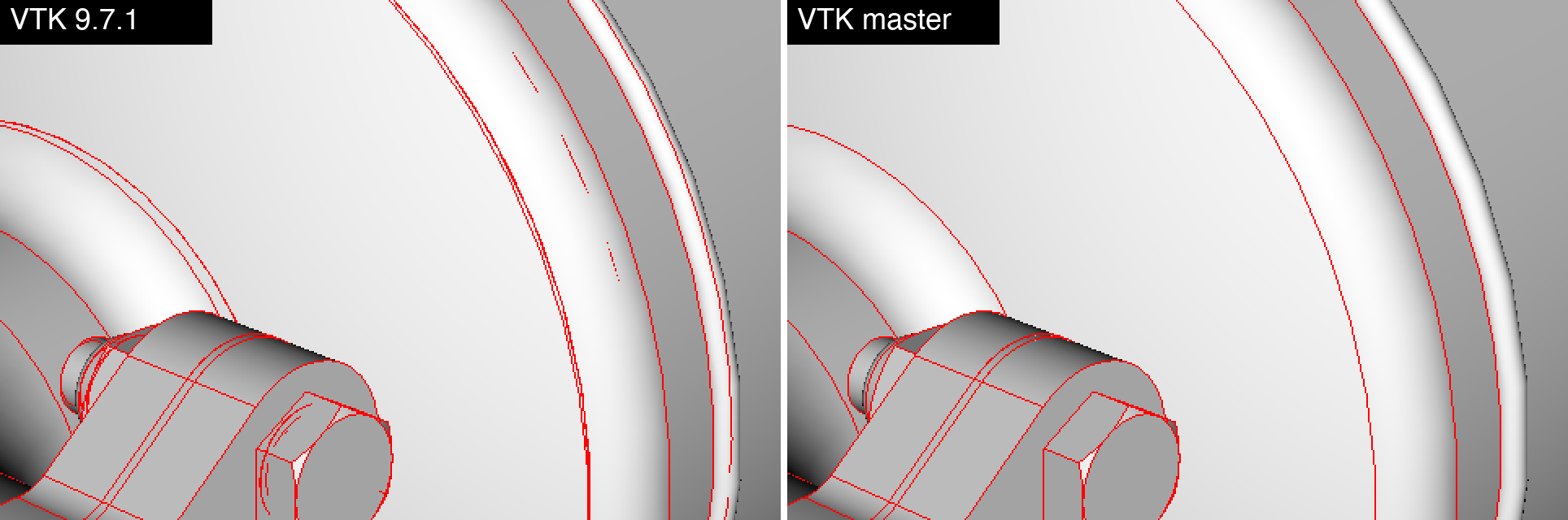
Model: I chose an exhaust system assembly exported from CAD as glTF (Porous_Exhaust_Assembly.glb, 549k points, 328k triangles). The file stores the CAD edges as line primitives next to each surface. I drew all surfaces with one actor and all edges with a second actor in red. Both images use the same camera and
SetResolveCoincidentTopologyToPolygonOffset() with line offset parameters (factor=0, units=-4), which are VTK’s defaults. The only difference is the VTK version. All images are 1920×1080 renders. The zooms are crops enlarged 2 times.
The goal here is that we want the lines to appear crisp on top of the polygons. I turned off antialiasing to clearly illustrate the pixels corresponding to the lines.
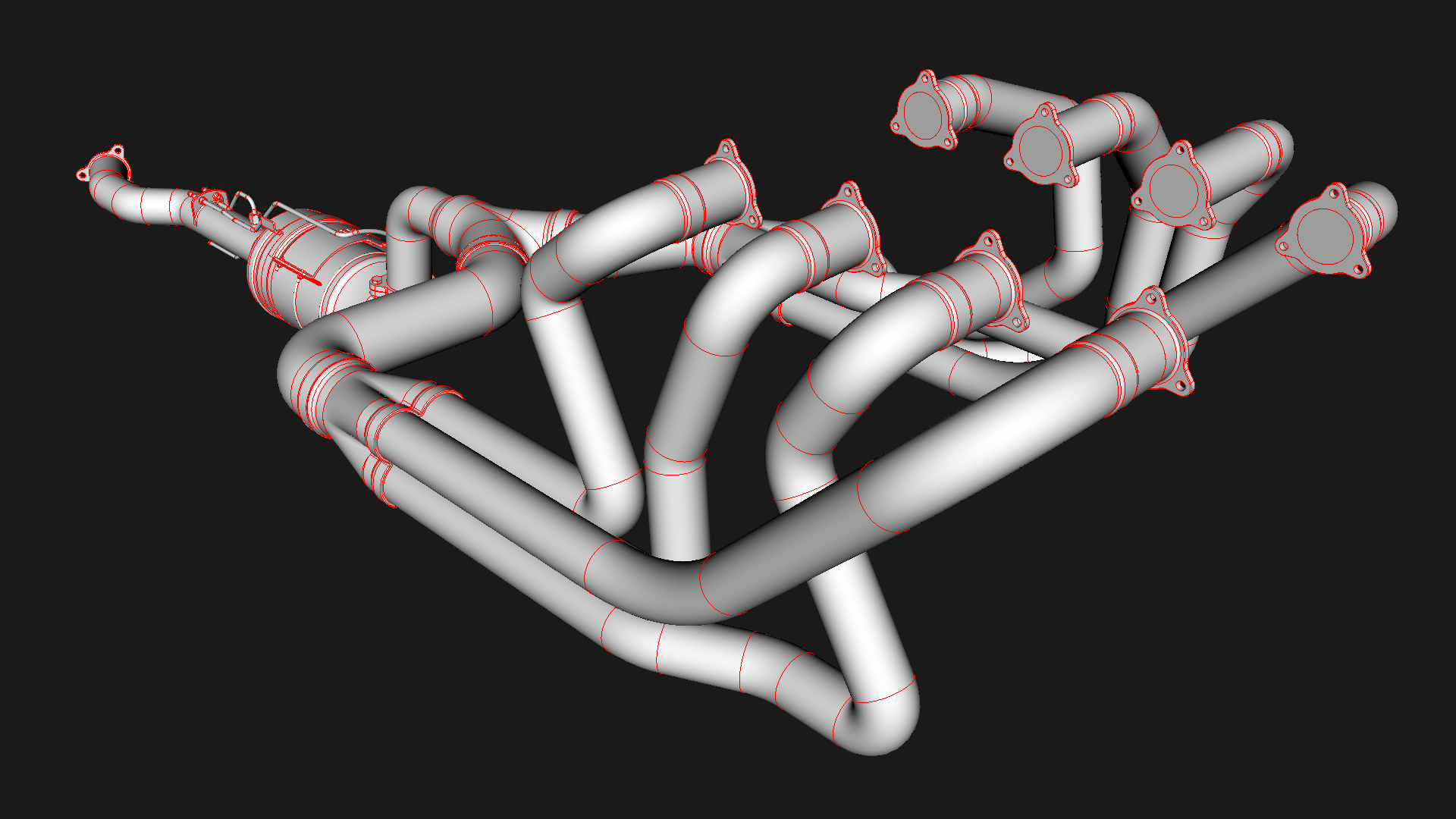
Bleed-through shows up once you zoom in, because the near clipping plane then moves close to the camera. The overviews below are close-ups of the assembly. The boxes mark the zooms.
Overview 1: boxes 1 and 2
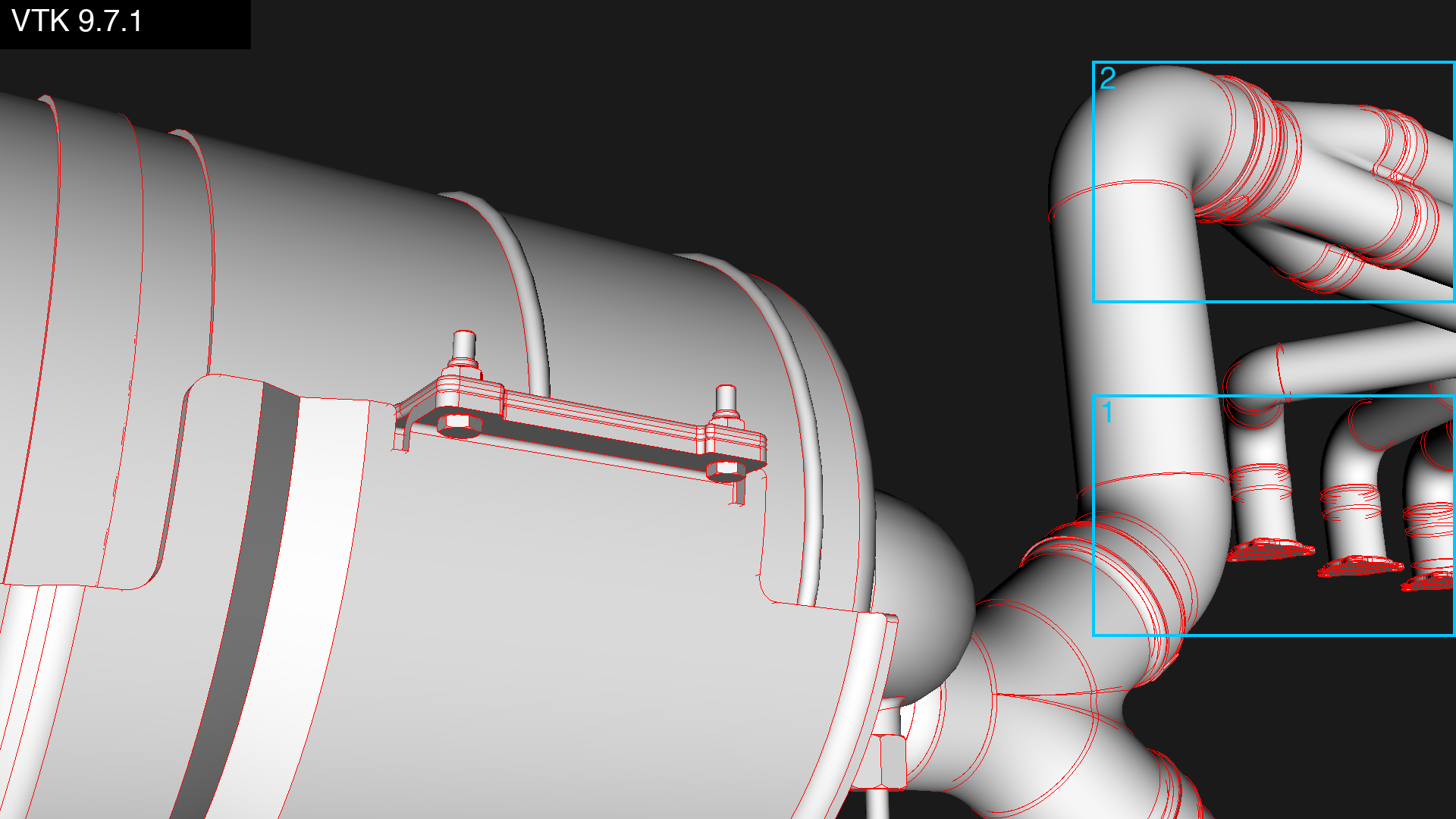
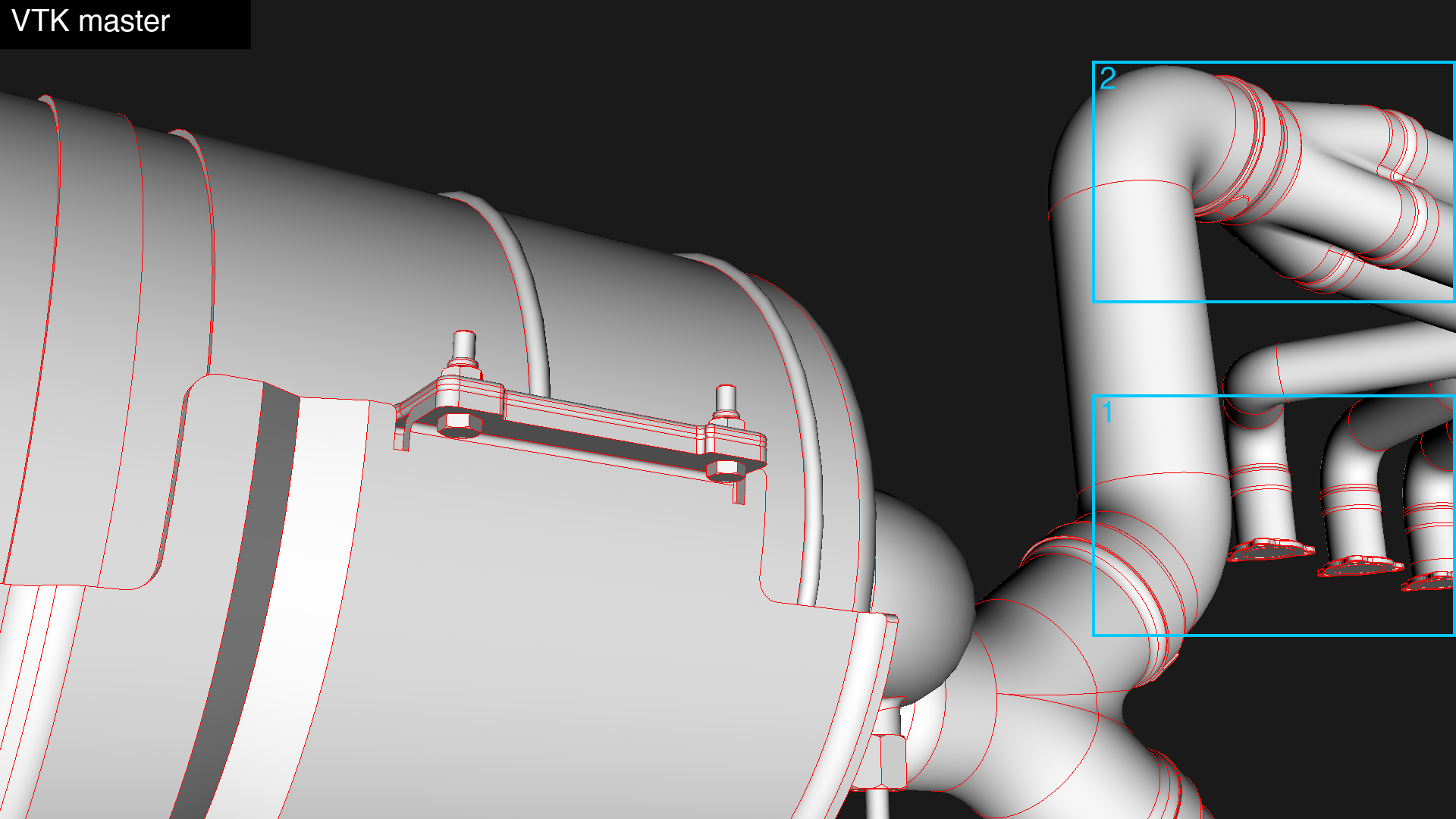
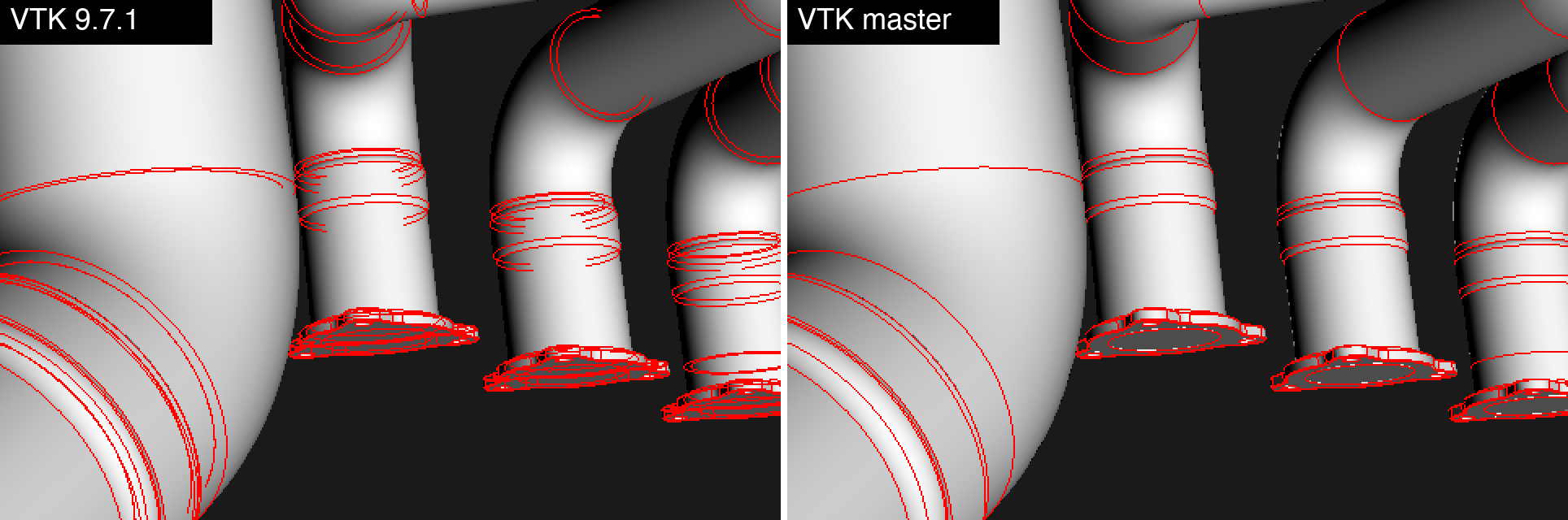
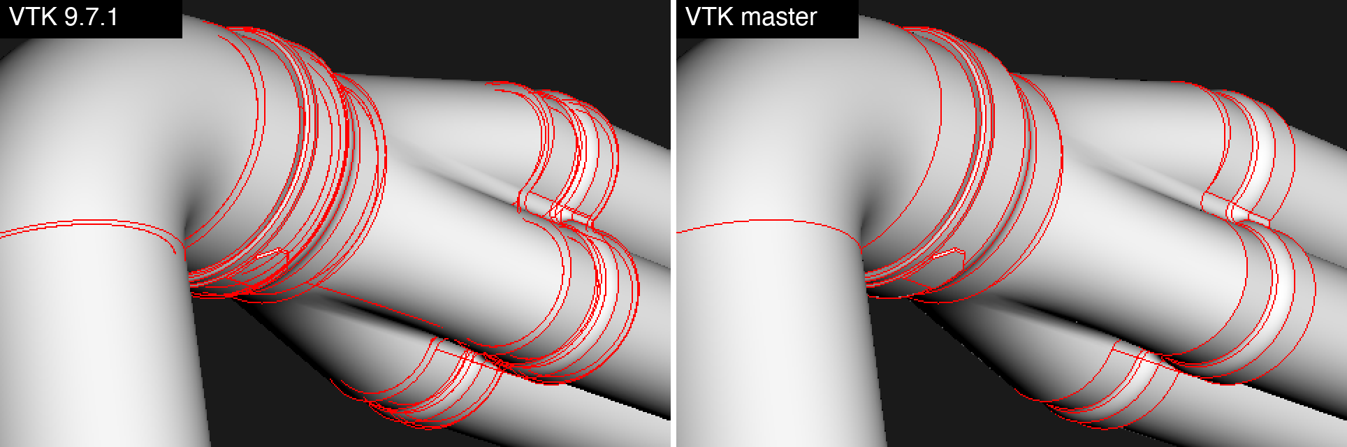
Zoom 1: pipes and flanges. In 9.7.1, each pipe shows a stack of partial rings, and the flanges are covered in a tangle of lines. These are edges on the far side of the pipe walls and flanges. master draws only the seams that face the camera.
Zoom 2: pipe sleeves. Where sleeves fit over the pipes, 9.7.1 shows the edges of the inner pipe and of the back of each sleeve through the sleeve wall. In master, the sleeve outlines are clean.
Overview 2: boxes 3 and 4
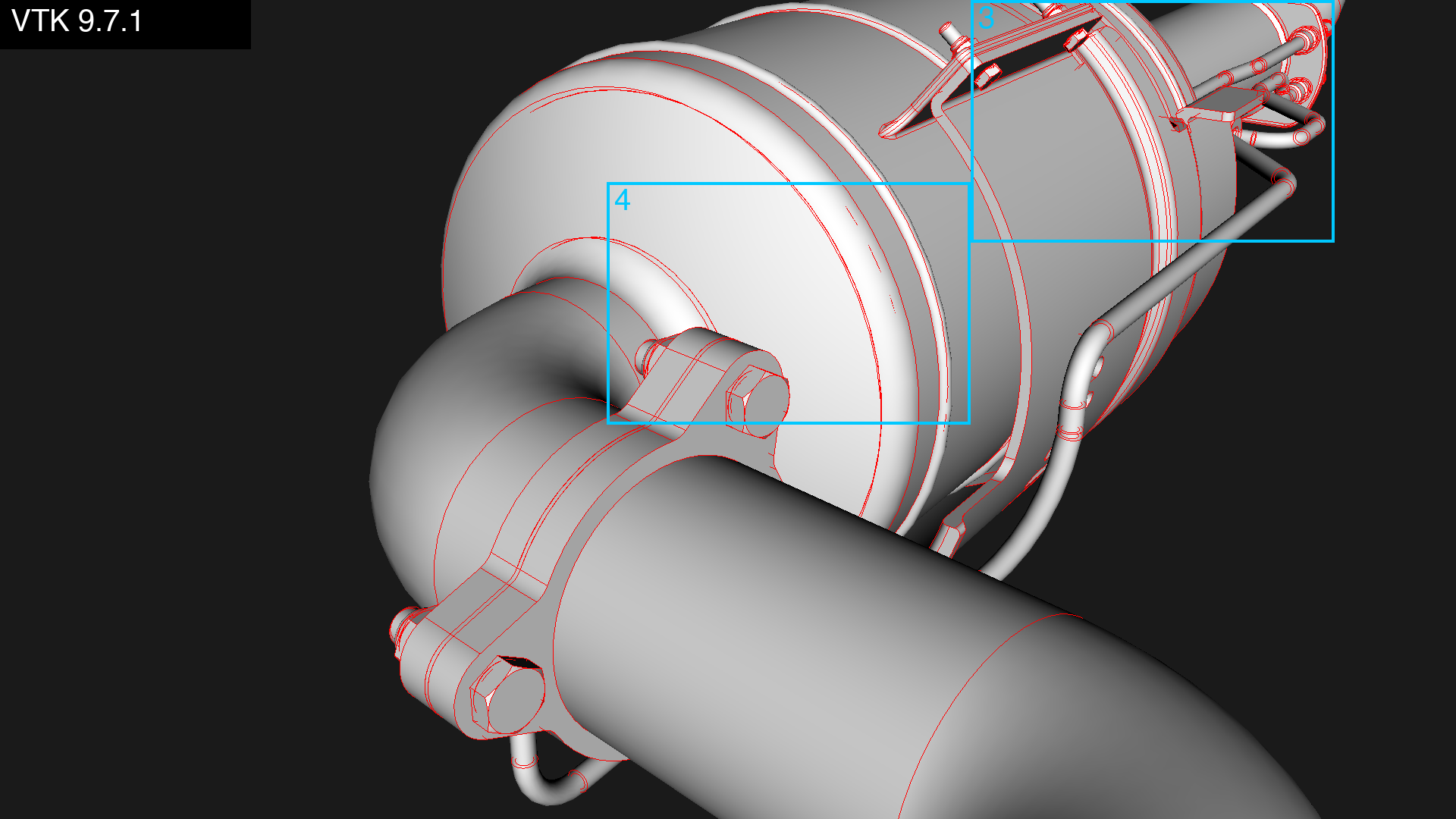
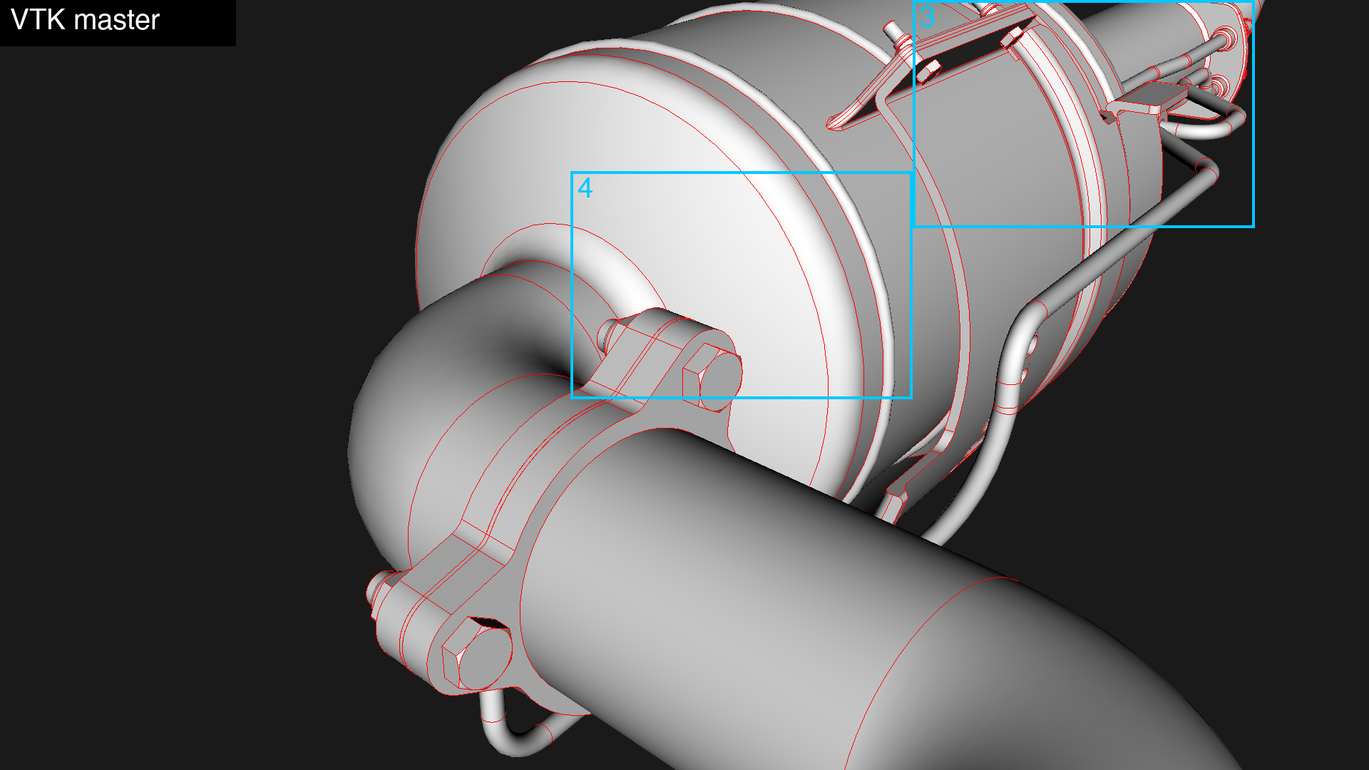
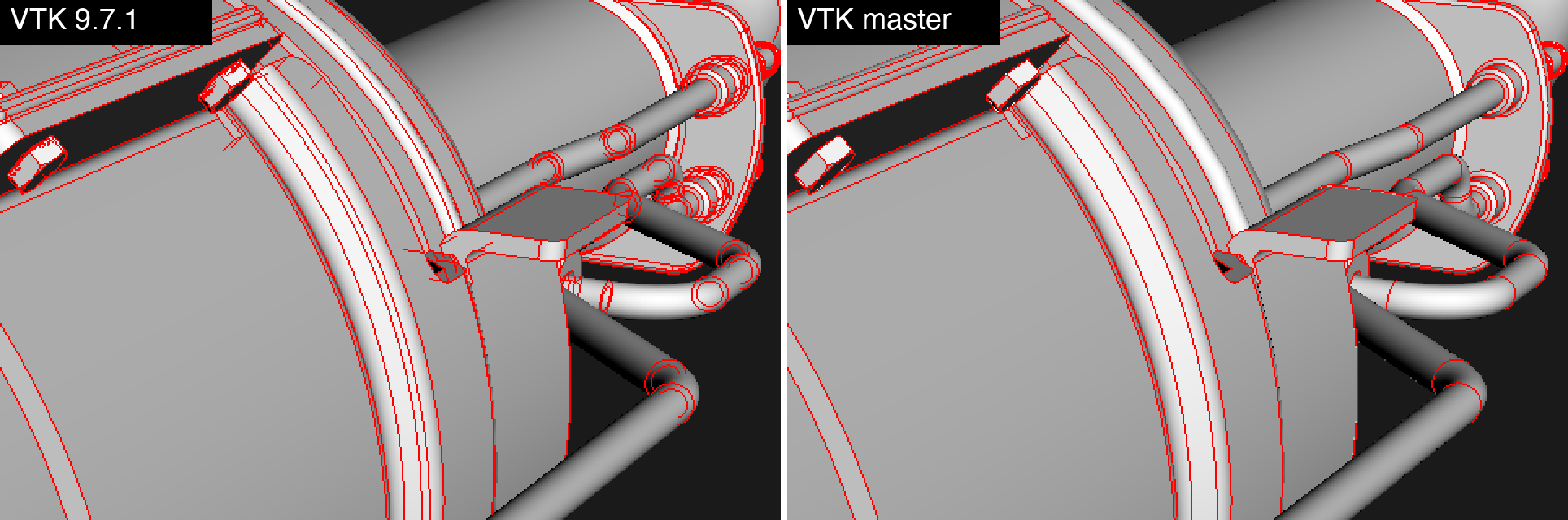
Zoom 3: converter bracket. In 9.7.1, nested circles from hidden bolt holes and tube ends show through the end flange, and stray segments cross the bracket. master is clean.
Zoom 4: clamp and end cap. In 9.7.1, the converter end cap shows doubled arcs and short dashes from the surface behind it, and the clamp and nut have extra outlines. In master, each edge is drawn once.
Do I need to change anything?
Most applications don’t need to change anything. You get the fix just by updating VTK.
If you set your own units with SetResolveCoincidentTopologyLineOffsetParameters, SetResolveCoincidentTopologyPointOffsetParameter, or the polygon or relative variants, those values now move geometry about 256x less on a 24-bit or 32-bit depth buffer.
If you had raised units to work around z-fighting, you may need to raise them further.
If you had lowered them to work around bleed-through, you can probably go back to the defaults.