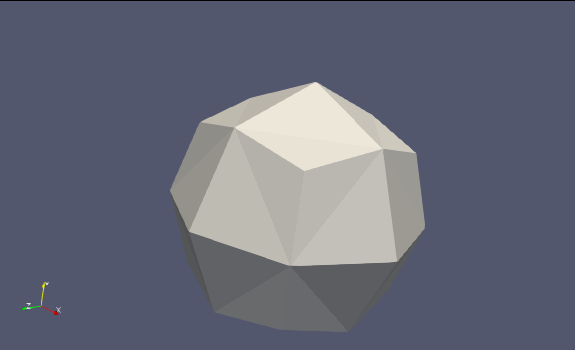
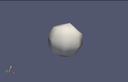
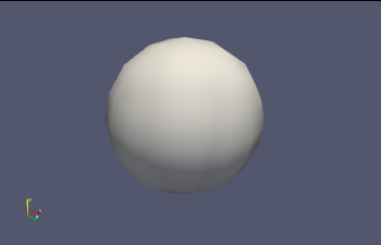
Actually I found out that I can increase the “nonlinear subdivision level” - and already with 2 instead of 1 everything looks very nice:
I am generating that dataset programmatically: a reader reads a table with georeferenced samples, and these are then represented as an “unstructured grid” with cells that are supposed to be kind of spheres. The reason for this is that single “samples” or groups should be selectable via “select cells”. If I generate spheres e.g. by first generating points in space and then apply a “glyph” filter, “cells” will be the single triangles, not the spheres!
Now I can tell the user of course that he should go to the “Display” property panel and change the “nonlinear subdivision factor” from 1 to 2, but I would still prefer to see this happening by default as soon as the reader has generated the data set. So right now I am trying to find the little screw where I can adapt the behaviour in this sense:
anything that I can add to the “unstructured grid” or it’s nonlinear “cells”? No way I can see…
right now I am trying instead to generate some kind of surface representation with nonlinear subdivision 2 by default - either with just an XML or writing some plugin code. With that I could put a “hint” in the reader’s XML to use that specialized surface view by default - et voilà!
If there is any easier way I would be happy with helpful hints and tipps!
Why “Select cells” can not be replaced by “Select Points”? As thing will be more efficient especially if you use the Glyph mapper rather than the glyph filter.
But I did not tell the full story, and I am not sure if it is really of interest; it is related with other design decisions in other parts of my custom software. (Which of course could also be different…)
One point is that the sample reader can not only handle single samples, to be represented by points, but also drillholes with a length - which I intend to represent with other “cell” types once everything works fine with the single samples. And these elongated samples will then again be cells, no matter what, so I believe that for the users it woud be easiest if all is somehow the same.
Right now I found a solution that may not be the most direct way, but maybe useful also for other cases later on: I wrote some “representation behaviour” class that is called on opening any kind of representation, and there I can see which source and SM proxies are there and adapt certain properties like I need them.
For the moment, the relevant piece of code is simply this:
Later on I may find occasions when I want to finetune the output of certain sources/filters etc. in a specific way, and I will be able to simply add another few lines.