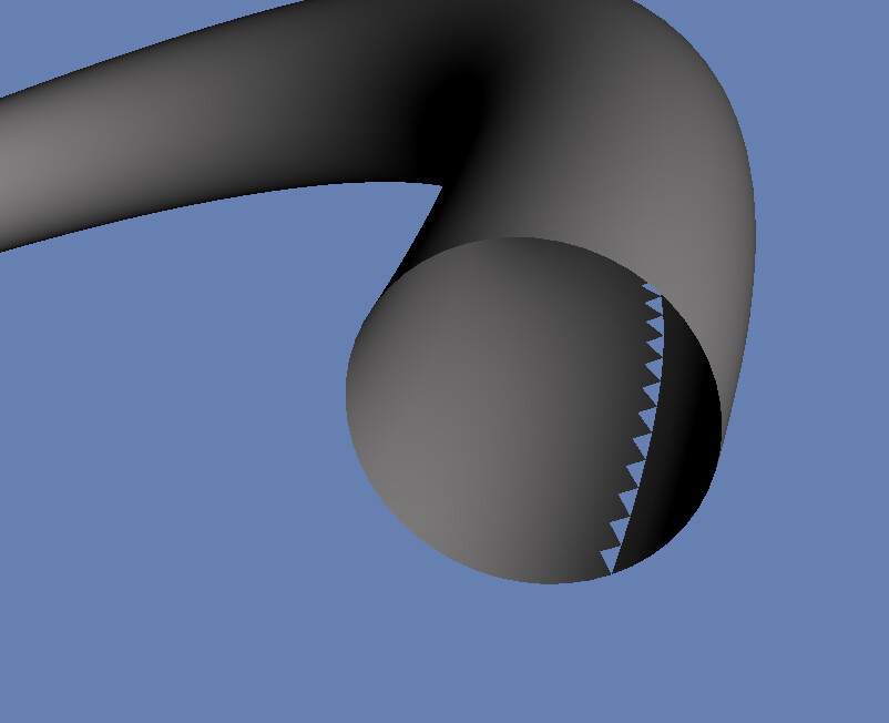
I tried to use vtkRuledSurfaceFilter to extrude a circle along a spline curve, but some error unexpected happened as shown in the figure below.Some triangle cells are just missed after this option and I have tried all the parametres but got nothing.After looking up the source code, I thought that should be a bug in the code that miss the cell that connects the last and the first point in a loop.
And I beg for some solutions to help solve this.
Can you please send some data and a simple program?
the code:
 vtkNew<vtkNamedColors> colors;
 vtkNew<vtkRegularPolygonSource> polygonSource;
 polygonSource->GeneratePolygonOff();
 polygonSource->SetNumberOfSides(50);
 polygonSource->SetRadius(2);
 polygonSource->SetCenter(0, 0, 0);
 polygonSource->Update();
 vtkSmartPointer<vtkPolyData> polyData = polygonSource->GetOutput();
 int numberOfContours = polyData->GetNumberOfLines();
 std::cout << "Number of contours: " << numberOfContours << std::endl;
 // Generate  some random points

 double start[3] = {-1.2, 0.0, 0.2};
 double p0[3] = {-1.0, 0.0, 0.0};
 double p1[3] = {0.0, 0.0, 0.0};

 // Create a vtkPoints object and store the points in it
 vtkNew<vtkPoints> points;
 points->InsertNextPoint(start);
 points->InsertNextPoint(p0);
 points->InsertNextPoint(p1);

 vtkNew<vtkParametricSpline> spline;
 spline->SetPoints(points);

 vtkNew<vtkParametricFunctionSource> functionSource;
 functionSource->SetParametricFunction(spline);
 functionSource->SetUResolution(100);
 functionSource->SetVResolution(100);
 functionSource->SetWResolution(100);
 functionSource->Update();

 // Create the frame
 vtkNew<vtkFrenetSerretFrame> frame;
 frame->SetInputConnection(functionSource->GetOutputPort());
 frame->ConsistentNormalsOn();
 frame->Update();

 frame->GetOutput()->GetPointData()->SetActiveVectors("FSNormals");
 frame->GetOutput()->GetPointData()->SetActiveVectors("FSTangents");
 frame->GetOutput()->GetPointData()->SetActiveVectors("FSBinormals");

 vtkPoints* linePoints = frame->GetOutput()->GetPoints();

 std::vector<vtkSmartPointer<vtkAppendPolyData>> skeletons;
 for (int i = 0; i < numberOfContours; ++i) {
     skeletons.push_back(vtkSmartPointer<vtkAppendPolyData>::New());
 }

 for (int i = 0; i < linePoints->GetNumberOfPoints(); ++i) {
     vtkNew<vtkTransform> transform;
     // Compute a basis
     double normalizedX[3];
     frame->GetOutput()->GetPointData()->SetActiveVectors("FSNormals");
     frame->GetOutput()->GetPointData()->GetVectors()->GetTuple(i, normalizedX);
     double normalizedY[3];
     frame->GetOutput()->GetPointData()->SetActiveVectors("FSBinormals");
     frame->GetOutput()->GetPointData()->GetVectors()->GetTuple(i, normalizedY);
     double normalizedZ[3];
     frame->GetOutput()->GetPointData()->SetActiveVectors("FSTangents");
     frame->GetOutput()->GetPointData()->GetVectors()->GetTuple(i, normalizedZ);

     // Create the direction cosine matrix
     vtkNew<vtkMatrix4x4> matrix;
     matrix->Identity();
     for (unsigned int j = 0; j < 3; ++j) {
         matrix->SetElement(j, 0, normalizedX[j]);
         matrix->SetElement(j, 1, normalizedY[j]);
         matrix->SetElement(j, 2, normalizedZ[j]);
     }
     transform->Translate(linePoints->GetPoint(i)[0], linePoints->GetPoint(i)[1],
                          linePoints->GetPoint(i)[2]);
     transform->Scale(.02, .02, .02);
     transform->Concatenate(matrix);

     vtkNew<vtkTransformPolyDataFilter> transformPD;
     vtkNew<vtkPolyData> polyDataCopy;
     polyDataCopy->DeepCopy(polyData);

     transformPD->SetTransform(transform);
     transformPD->SetInputData(polyDataCopy);
     transformPD->Update();

     vtkNew<vtkPolyDataConnectivityFilter> contours;
     contours->SetInputConnection(transformPD->GetOutputPort());
     contours->Update();
     for (int r = 0; r < contours->GetNumberOfExtractedRegions(); ++r)
     {
         contours->SetExtractionModeToSpecifiedRegions();
         contours->InitializeSpecifiedRegionList();
         contours->AddSpecifiedRegion(r);
         contours->Update();
         vtkNew<vtkPolyData> skeleton;
         skeleton->DeepCopy(contours->GetOutput());
         skeletons[r]->AddInputData(skeleton);
     }
 }
 for (int i = 0; i < numberOfContours; ++i) {
     vtkNew<vtkRuledSurfaceFilter> ruled;
     ruled->SetRuledModeToPointWalk();
     ruled->CloseSurfaceOff();
     ruled->SetOnRatio(0);
     ruled->SetOffset(10);
     ruled->OrientLoopsOn();
     ruled->SetDistanceFactor(10000000);
     ruled->SetInputConnection(skeletons[i]->GetOutputPort());
     std::cout << ruled->GetOffset() << endl;

     vtkNew<vtkPolyDataNormals> normals;
     normals->SetInputConnection(ruled->GetOutputPort());
     vtkNew<vtkPolyDataMapper> mapper;
     mapper->SetInputConnection(normals->GetOutputPort());
     vtkNew<vtkActor> actor;
     actor->GetProperty()->SetColor(colors->GetColor3d("Snow").GetData());
     actor->SetMapper(mapper);
     modelStore.renderer->AddActor(actor);
 }
 modelStore.renderer->SetBackground(.4, .5, .7);
 modelStore.renderWindow->AddRenderer(modelStore.renderer);
 ui.openGLWidget->setRenderWindow(modelStore.renderWindow);
 ui.openGLWidget->setVisible(true);
Hi 段凡,
I am having some problems when applying the vtkFrenetSerretFrame class in a qt c++ vtk program. Do you have any tips when you implemented your codes?
Kind regards,
Yuxuan
Hi,
I have made a code example that shows exactly the same problem reported by the original poster using vtkRuledSurfaceFilter with PointWalk mode ![]()
All the code is vtk, except I had to replace vtk.vtkFrenetSerretFrame() with slicer.vtkParallelTransportFrame()
# Create profile
vtk.vtkMath.RandomSeed(7859821)

diskSource = vtk.vtkDiskSource()
diskSource.SetCircumferentialResolution(5)

clean = vtk.vtkCleanPolyData()
clean.SetInputConnection(diskSource.GetOutputPort())

edges = vtk.vtkFeatureEdges()
edges.SetInputConnection(clean.GetOutputPort())
edges.NonManifoldEdgesOff()
edges.ManifoldEdgesOff()
edges.BoundaryEdgesOn()
edges.FeatureEdgesOff()

stripper = vtk.vtkStripper()
stripper.SetInputConnection(edges.GetOutputPort())
stripper.Update()
profilePolyData = stripper.GetOutput()


# Create a parametric spline
## Generate  some random points
numberOfPoints = 5
pointSource = vtk.vtkPointSource()
pointSource.SetNumberOfPoints(numberOfPoints)
pointSource.Update()

points = pointSource.GetOutput().GetPoints()

## Generate the spline
spline = vtk.vtkParametricSpline()
spline.SetPoints(points)

functionSource = vtk.vtkParametricFunctionSource()
functionSource.SetParametricFunction(spline)
functionSource.SetUResolution(50 * numberOfPoints)
functionSource.SetVResolution(50 * numberOfPoints)
functionSource.SetWResolution(50 * numberOfPoints)
functionSource.Update()
splinePolyData = functionSource.GetOutput()


# Create the frame
frame = slicer.vtkParallelTransportFrame() # equivalent to vtk.vtkFrenetSerretFrame()
frame.SetInputData(splinePolyData)
frame.Update()

frame.GetOutput().GetPointData().SetActiveVectors("Normals")
frame.GetOutput().GetPointData().SetActiveVectors("Tangents")
frame.GetOutput().GetPointData().SetActiveVectors("Binormals")

linePoints = frame.GetOutput().GetPoints()

skeleton = vtk.vtkAppendPolyData()
for i in range(linePoints.GetNumberOfPoints()):
    transform = vtk.vtkTransform()

    # Compute a basis
    normalizedX = [0, 0, 0]
    frame.GetOutput().GetPointData().SetActiveVectors("Normals")
    frame.GetOutput().GetPointData().GetVectors().GetTuple(i, normalizedX)
    normalizedY = [0, 0, 0]
    frame.GetOutput().GetPointData().SetActiveVectors("Binormals")
    frame.GetOutput().GetPointData().GetVectors().GetTuple(i, normalizedY)
    normalizedZ = [0, 0, 0]
    frame.GetOutput().GetPointData().SetActiveVectors("Tangents")
    frame.GetOutput().GetPointData().GetVectors().GetTuple(i, normalizedZ)

    # Create the direction cosine matrix
    matrix = vtk.vtkMatrix4x4()
    matrix.Identity()
    for j in range(3):
        matrix.SetElement(j, 0, normalizedX[j])
        matrix.SetElement(j, 1, normalizedY[j])
        matrix.SetElement(j, 2, normalizedZ[j])

    transform.Translate(linePoints.GetPoint(i)[0], linePoints.GetPoint(i)[1],
                            linePoints.GetPoint(i)[2])
    transform.Scale(.02, .02, .02)
    transform.Concatenate(matrix)

    transformPD = vtk.vtkTransformPolyDataFilter()
    polyDataCopy = vtk.vtkPolyData()
    polyDataCopy.DeepCopy(profilePolyData)

    transformPD.SetTransform(transform)
    transformPD.SetInputData(polyDataCopy)
    transformPD.Update()

    contours = vtk.vtkPolyDataConnectivityFilter()
    contours.SetInputConnection(transformPD.GetOutputPort())
    contours.SetExtractionModeToLargestRegion()
    contours.Update()
    skeleton.AddInputData(contours.GetOutput())


ruled = vtk.vtkRuledSurfaceFilter()
ruled.SetRuledModeToPointWalk()
ruled.CloseSurfaceOff()
ruled.SetOnRatio(1)
ruled.SetDistanceFactor(10000000)
ruled.SetOrientLoops(True)
ruled.SetInputConnection(skeleton.GetOutputPort())
ruled.Update()


# Slicer code
modelsLogic = slicer.modules.models.logic()
profileModel = modelsLogic.AddModel(profilePolyData)
splineModel = modelsLogic.AddModel(splinePolyData)
skeletonModel = modelsLogic.AddModel(skeleton.GetOutput())
ruledExtrusionModel = modelsLogic.AddModel(ruled.GetOutput())
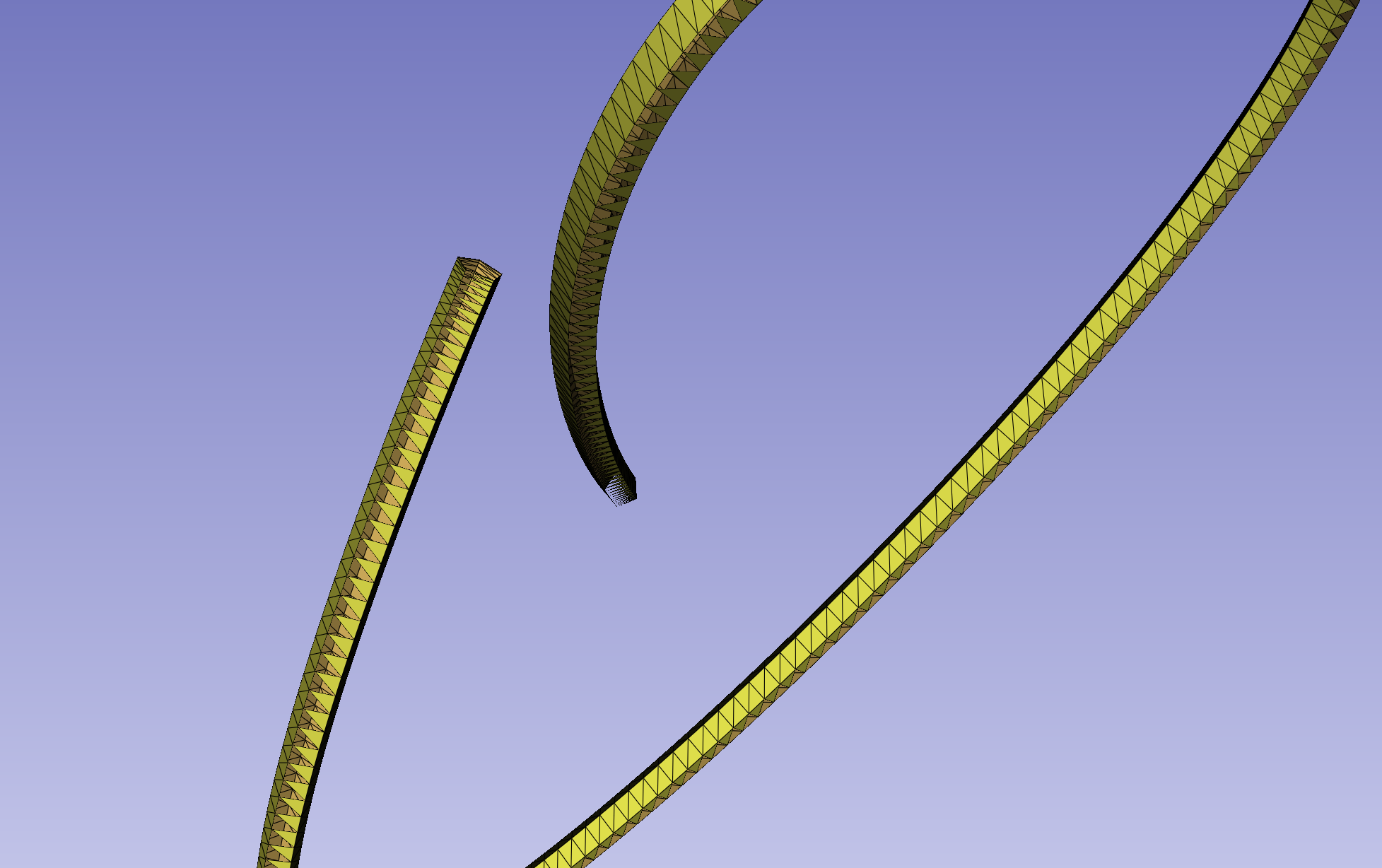
Please see figures below that show the missing triangle between each neighboring loops triangles creation
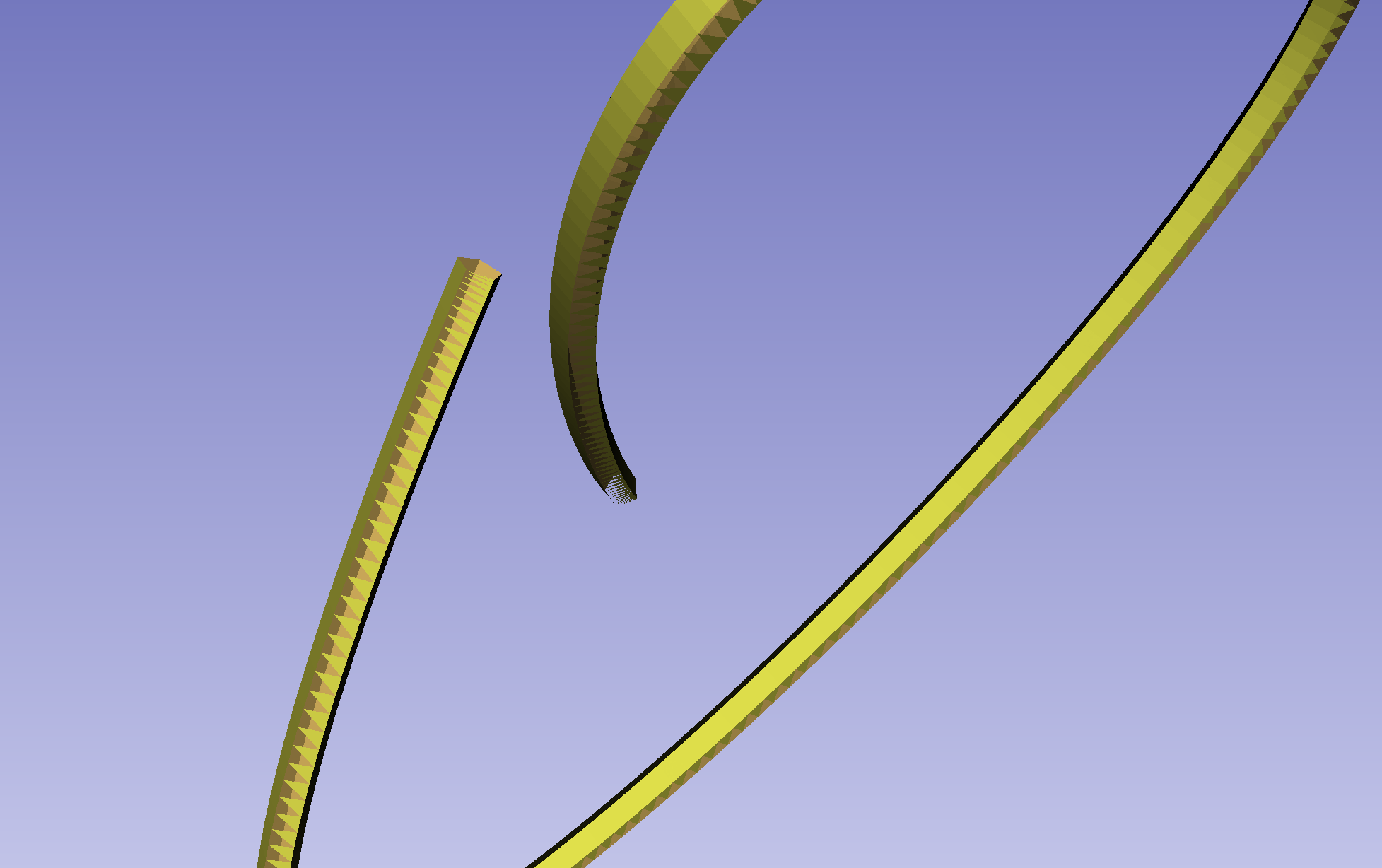
Thank you ![]()
![]()
![]()
Hi,
I just wanted to write again to see if someone has feedback on this problem
Thank you
Does anyone have any hints in how to solve it? I may be able to put time into fixing it
It’s likely that there is an indexing problem that causes triangles to be dropped, or even possibly degenerate triangles created. etc. I suggest that you create a minimal example, and then walk through the code to see what’s going on. We’ve seen this problem before, so if you can help solve it that would be great.
1 Like
Hi
Here is a straight-forward example with python’s vtk
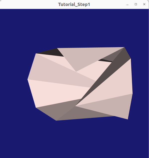
(Please note the missing triangle in front of the picture)
Code below:
def polylineSource(numberOfSides):
    polygonSource = vtk.vtkRegularPolygonSource()
    polygonSource.SetNumberOfSides(numberOfSides)
    polygonSource.SetRadius(1.0)
    polygonSource.SetCenter(0, 0, 0)
    polygonSource.GeneratePolygonOff()
    polygonSource.GeneratePolylineOn()
    polygonSource.Update()
    return polygonSource.GetOutput()

polyline = polylineSource(numberOfSides=7)

transform = vtk.vtkTransform()
transform.PostMultiply()
transform.RotateX(15)
transform.RotateY(45)
transform.RotateZ(30)
transform.Translate(0, 0, -2)

transformFilter = vtk.vtkTransformPolyDataFilter()
transformFilter.SetTransform(transform)
transformFilter.SetInputData(polyline)
transformFilter.Update()
transformedPolyline = transformFilter.GetOutput()

appendedPolylines = vtk.vtkAppendPolyData()
appendedPolylines.AddInputData(polyline)
appendedPolylines.AddInputData(transformedPolyline)
appendedPolylines.Update()

ruledSurfaceFilter = vtk.vtkRuledSurfaceFilter()
ruledSurfaceFilter.SetRuledModeToPointWalk()
ruledSurfaceFilter.CloseSurfaceOff()
ruledSurfaceFilter.SetOnRatio(1)
ruledSurfaceFilter.SetDistanceFactor(10000000)
ruledSurfaceFilter.SetOrientLoops(True)
ruledSurfaceFilter.SetInputData(appendedPolylines.GetOutput())
ruledSurfaceFilter.Update()


# From this rendering example:
# https://examples.vtk.org/site/Python/Tutorial/Tutorial_Step1/
coneMapper = vtk.vtkPolyDataMapper()
coneMapper.SetInputConnection(ruledSurfaceFilter.GetOutputPort())

coneActor = vtk.vtkActor()
coneActor.SetMapper(coneMapper)
colors = vtk.vtkNamedColors()
coneActor.GetProperty().SetColor(colors.GetColor3d('MistyRose'))

ren1 = vtk.vtkRenderer()
ren1.AddActor(coneActor)
ren1.SetBackground(colors.GetColor3d('MidnightBlue'))

renWin = vtk.vtkRenderWindow()
renWin.AddRenderer(ren1)
renWin.SetSize(600, 600)
renWin.SetWindowName('Tutorial_Step1')

for i in range(0, 270):
    # Render the image
    renWin.Render()
    # Rotate the active camera by one degree.
    ren1.GetActiveCamera().Azimuth(1)


# Slicer code to visualize the models
#modelsLogic = slicer.modules.models.logic()
#triangleModel = modelsLogic.AddModel(polyline)
#pentagonModel = modelsLogic.AddModel(transformedPolyline)
#bothModel = modelsLogic.AddModel(appendedPolylines.GetOutput())
#ruledExtrusionModel = modelsLogic.AddModel(ruledSurfaceFilter.GetOutput())
As a side note, I tried adding some logging statements to the vtkRuledSurfaceFilter and I noted some things using different input data:
- A very high number of times the first if statement is never entered while executing the filter
- Sometimes the second if statement is never entered while executing the filter
- The third and forth if blocks are always entered by executing the filter
In my opinion this implies that the while loop that controls the creation of new triangles has some faulty logic.
Hope you can help
Mauro