Hi,
I have made a code example that shows exactly the same problem reported by the original poster using vtkRuledSurfaceFilter with PointWalk mode ![]()
All the code is vtk, except I had to replace vtk.vtkFrenetSerretFrame() with slicer.vtkParallelTransportFrame()
# Create profile
vtk.vtkMath.RandomSeed(7859821)

diskSource = vtk.vtkDiskSource()
diskSource.SetCircumferentialResolution(5)

clean = vtk.vtkCleanPolyData()
clean.SetInputConnection(diskSource.GetOutputPort())

edges = vtk.vtkFeatureEdges()
edges.SetInputConnection(clean.GetOutputPort())
edges.NonManifoldEdgesOff()
edges.ManifoldEdgesOff()
edges.BoundaryEdgesOn()
edges.FeatureEdgesOff()

stripper = vtk.vtkStripper()
stripper.SetInputConnection(edges.GetOutputPort())
stripper.Update()
profilePolyData = stripper.GetOutput()


# Create a parametric spline
## Generate  some random points
numberOfPoints = 5
pointSource = vtk.vtkPointSource()
pointSource.SetNumberOfPoints(numberOfPoints)
pointSource.Update()

points = pointSource.GetOutput().GetPoints()

## Generate the spline
spline = vtk.vtkParametricSpline()
spline.SetPoints(points)

functionSource = vtk.vtkParametricFunctionSource()
functionSource.SetParametricFunction(spline)
functionSource.SetUResolution(50 * numberOfPoints)
functionSource.SetVResolution(50 * numberOfPoints)
functionSource.SetWResolution(50 * numberOfPoints)
functionSource.Update()
splinePolyData = functionSource.GetOutput()


# Create the frame
frame = slicer.vtkParallelTransportFrame() # equivalent to vtk.vtkFrenetSerretFrame()
frame.SetInputData(splinePolyData)
frame.Update()

frame.GetOutput().GetPointData().SetActiveVectors("Normals")
frame.GetOutput().GetPointData().SetActiveVectors("Tangents")
frame.GetOutput().GetPointData().SetActiveVectors("Binormals")

linePoints = frame.GetOutput().GetPoints()

skeleton = vtk.vtkAppendPolyData()
for i in range(linePoints.GetNumberOfPoints()):
    transform = vtk.vtkTransform()

    # Compute a basis
    normalizedX = [0, 0, 0]
    frame.GetOutput().GetPointData().SetActiveVectors("Normals")
    frame.GetOutput().GetPointData().GetVectors().GetTuple(i, normalizedX)
    normalizedY = [0, 0, 0]
    frame.GetOutput().GetPointData().SetActiveVectors("Binormals")
    frame.GetOutput().GetPointData().GetVectors().GetTuple(i, normalizedY)
    normalizedZ = [0, 0, 0]
    frame.GetOutput().GetPointData().SetActiveVectors("Tangents")
    frame.GetOutput().GetPointData().GetVectors().GetTuple(i, normalizedZ)

    # Create the direction cosine matrix
    matrix = vtk.vtkMatrix4x4()
    matrix.Identity()
    for j in range(3):
        matrix.SetElement(j, 0, normalizedX[j])
        matrix.SetElement(j, 1, normalizedY[j])
        matrix.SetElement(j, 2, normalizedZ[j])

    transform.Translate(linePoints.GetPoint(i)[0], linePoints.GetPoint(i)[1],
                            linePoints.GetPoint(i)[2])
    transform.Scale(.02, .02, .02)
    transform.Concatenate(matrix)

    transformPD = vtk.vtkTransformPolyDataFilter()
    polyDataCopy = vtk.vtkPolyData()
    polyDataCopy.DeepCopy(profilePolyData)

    transformPD.SetTransform(transform)
    transformPD.SetInputData(polyDataCopy)
    transformPD.Update()

    contours = vtk.vtkPolyDataConnectivityFilter()
    contours.SetInputConnection(transformPD.GetOutputPort())
    contours.SetExtractionModeToLargestRegion()
    contours.Update()
    skeleton.AddInputData(contours.GetOutput())


ruled = vtk.vtkRuledSurfaceFilter()
ruled.SetRuledModeToPointWalk()
ruled.CloseSurfaceOff()
ruled.SetOnRatio(1)
ruled.SetDistanceFactor(10000000)
ruled.SetOrientLoops(True)
ruled.SetInputConnection(skeleton.GetOutputPort())
ruled.Update()


# Slicer code
modelsLogic = slicer.modules.models.logic()
profileModel = modelsLogic.AddModel(profilePolyData)
splineModel = modelsLogic.AddModel(splinePolyData)
skeletonModel = modelsLogic.AddModel(skeleton.GetOutput())
ruledExtrusionModel = modelsLogic.AddModel(ruled.GetOutput())
Please see figures below that show the missing triangle between each neighboring loops triangles creation
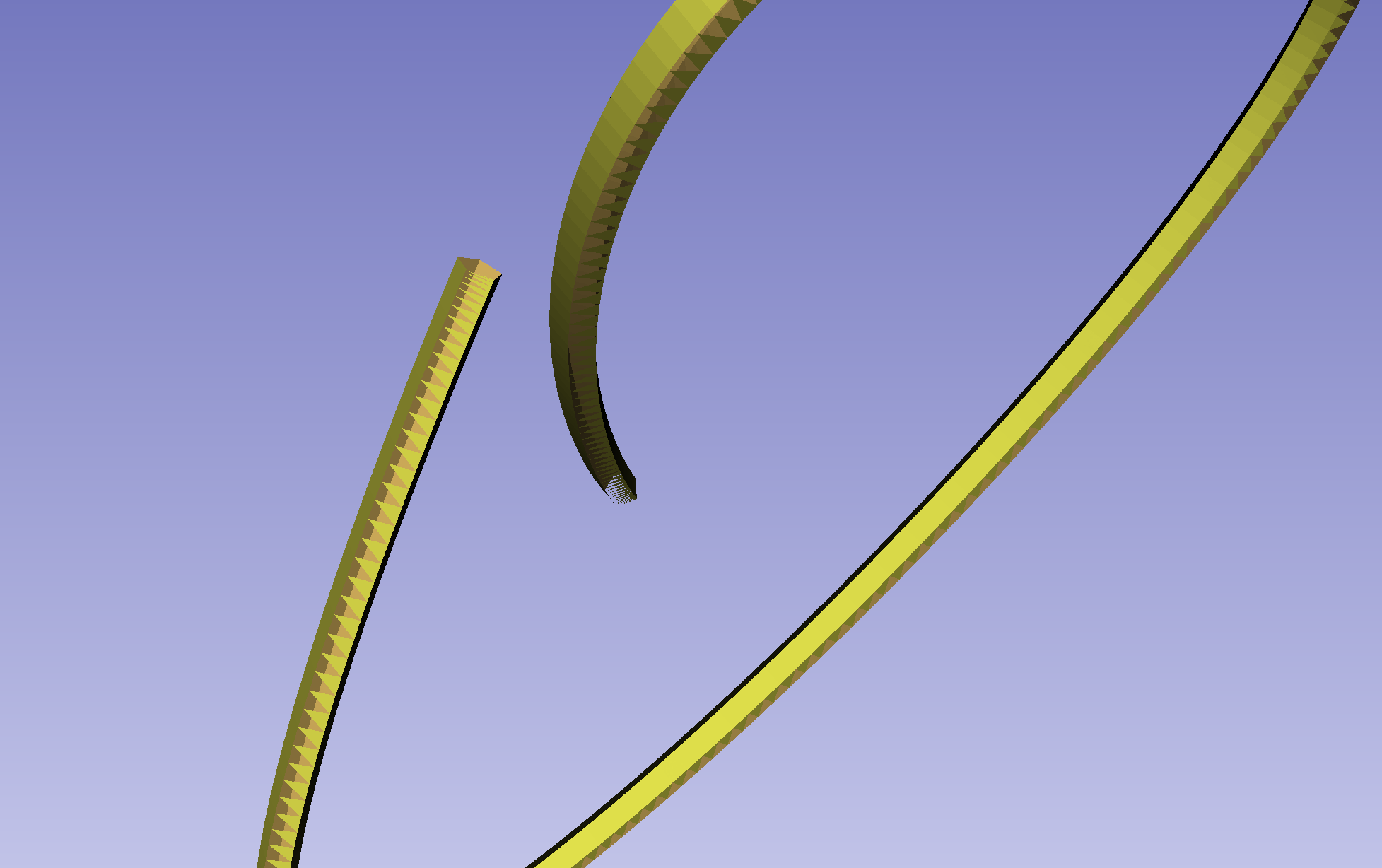
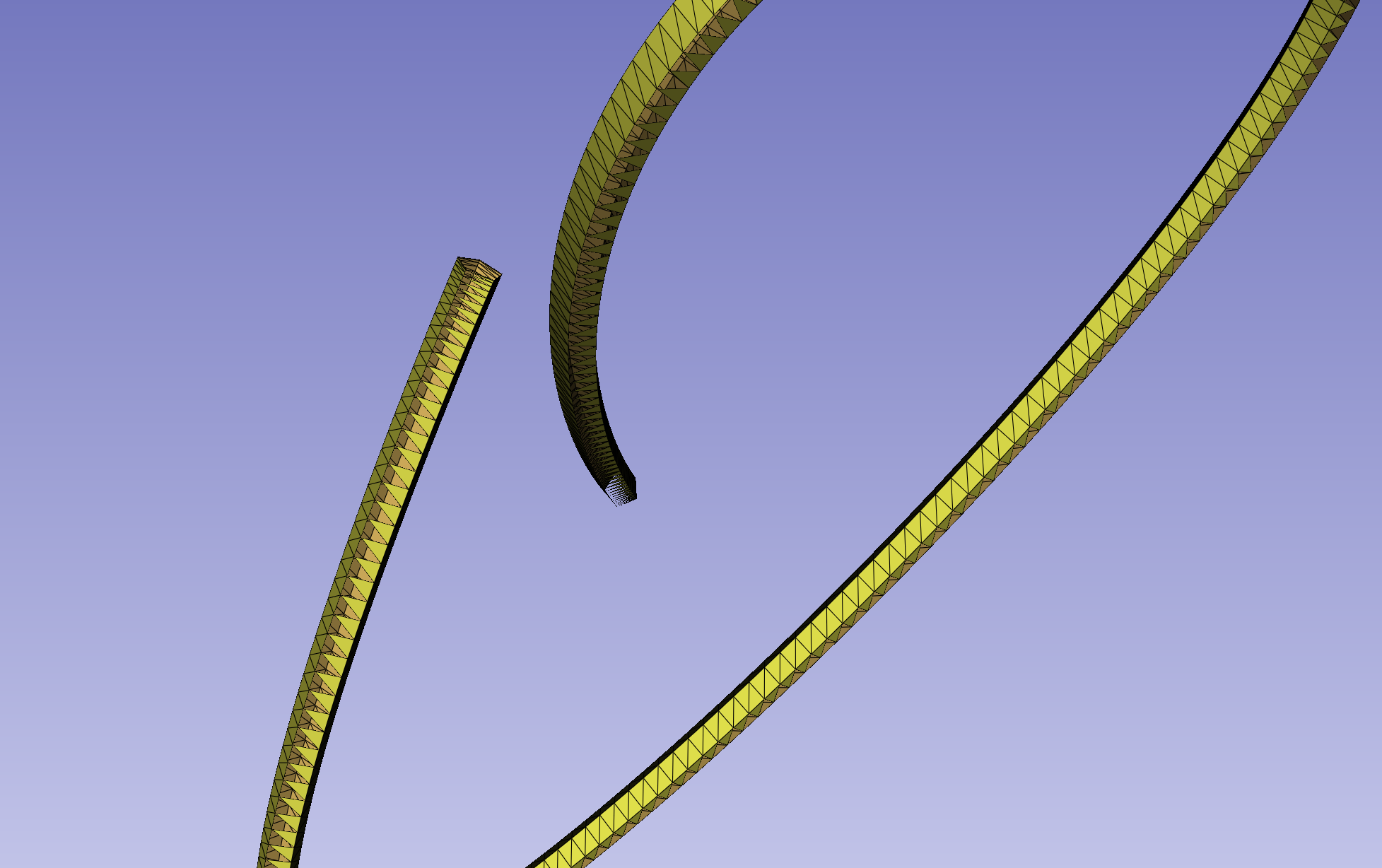
Thank you ![]()
![]()
![]()