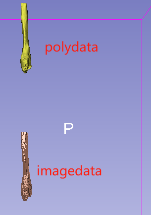
I use the following code to read the binary labelmap and convert it to polydata, in which I use vtkTransformPolyDataFilter to set the polydata’s transform, hoping to make the coordinate systems of the polydata and the input image the same. But I used slicer to read these two files and found that they did not overlap. Does this mean that their coordinate systems are not unified? If so, how can I unify them?
The QFormMatrix should not be inverted, since this matrix already produces RAS coords. Try it without the inversion:
transformIJKtoLPS = vtk.vtkTransform()
transformIJKtoLPS.Scale(-1.0, -1.0, 1.0)  # RAS to LPS
if reader.GetQFormMatrix() is not None:
    transformIJKtoLPS.Concatenate(reader.GetQFormMatrix())
Thank you very much, the method you provided solved the problem!
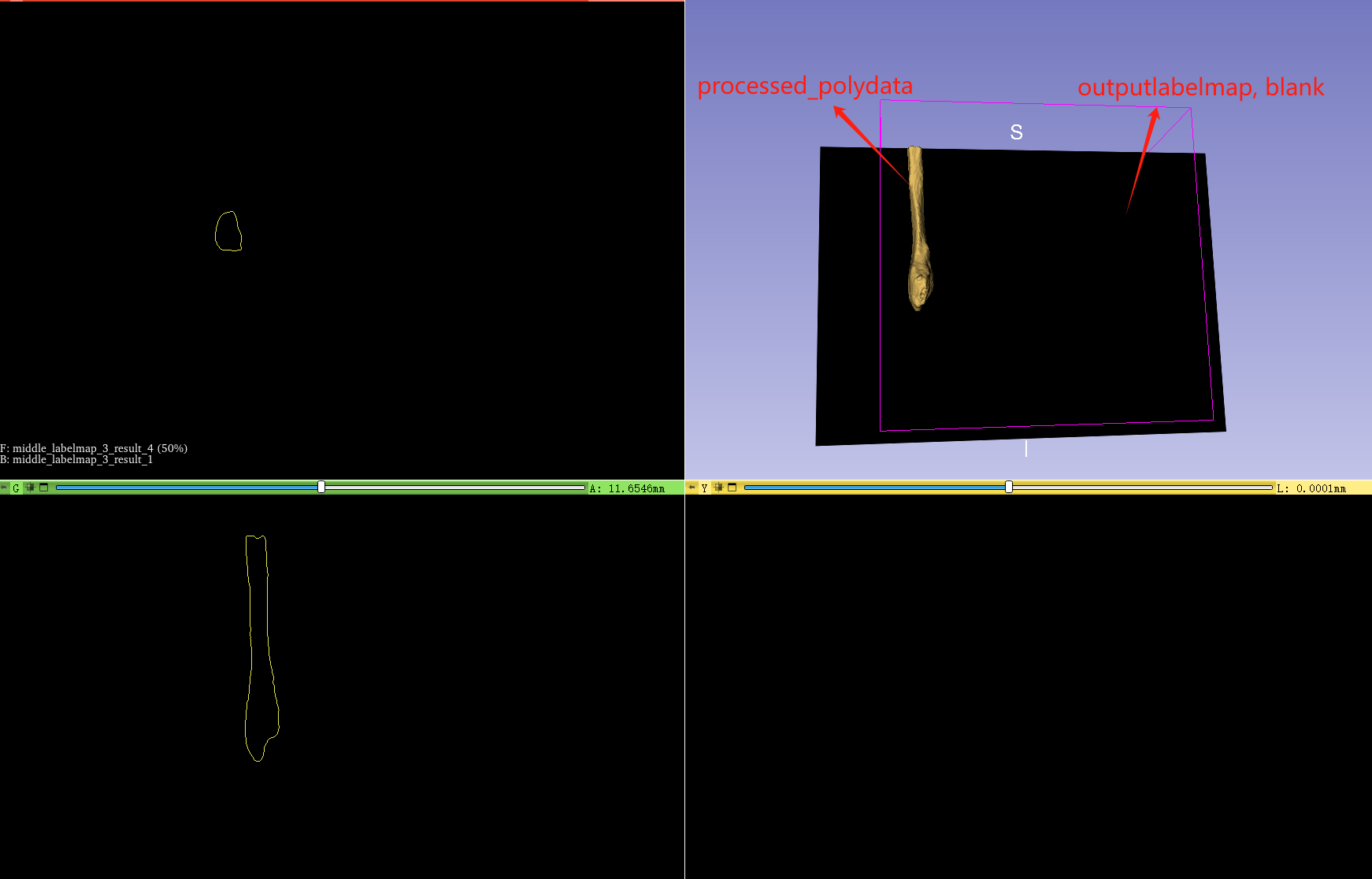
Now I encounter another problem. I get a polydata that is consistent with the coordinate system of the input label image. After a series of processing on it, I want to convert it into a label image. The code is as follows:
I used vtkPolyDataToImageStencil and vtkImageStencil to achieve this, I expected to get a label image with the same coordinate system as the input label image, but what I got was a blank image.
When I don’t use the information of the input label image, I can get a label image with annotations. However, I open it with slicer and it does not maintain the same coordinate system as the input label image.
Where’s your code for saving the label image? You will need something like this, to set the sform of the label image to be the same as the original image:
writer.SetSFormMatrix(reader.GetSFormMatrix())`
Also, unless you really need a 16-bit label image, I recommend using 8-bit instead, and for the sake of easy visualization you can fill with the maximum value:
The code where you call your function _polydataToLabelmap2() is also not shown above. When you create the label image, do you use the polydata before applying vtkTransformPolyData or after? For correct results, you’d need to call _polydataToLabelmap2() with the polydata that’s still using the same coords as the referenceImage, i.e. before applying the transformation.
This is the code that calls the _polydataToLabelmap2() function and saves the label image.
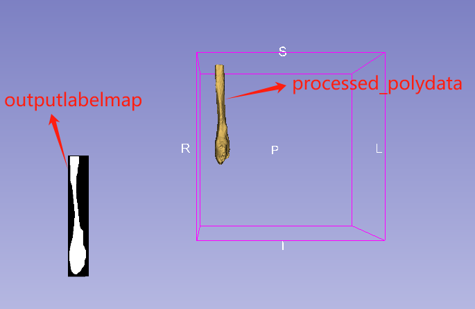
smoothedPd is obtained through a series of processing based on the polydata (inputPd) obtained by vtkDiscreteFlyingEdges3D and application of transformation. The transform is not changed in the middle. What you mean is that the _polydataToLabelmap2() function needs to input polydata with the same coordinate system as referenceImage. But smoothedPd does not comply, Can we set an opposite transform to smoothedPd? Or is there any other way?
My recommendation: don’t apply the transform to the polydata until just before you save it to disk. Perform the transformation the very last step. That way, you won’t need to apply an inverse transformation.
I Got it! From the beginning, the polydata obtained from the input label image already maintains the same coordinate system as the input image. I added a transformation to the polydata based on the slicer source code, and the purpose of this is just to make the polydata and the label image in the same coordinate system in the viewer. Now the problem has been solved, Thank you very much!