Axes Direction Cosines - please help

Hello,

I have a cube and vtkImageReslice in my code and 3 ordinary cutting planes (a.k.a axial, sagittal, coronal) that make slices of the cube content.

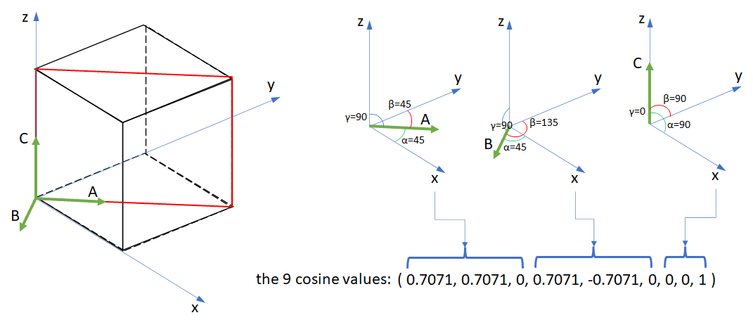
For these 3 planes I use the vtkImageReslice.SetResliceAxesDirectionCosines function.

I don’t know how to visualize this planes inside cube volume, so I don’t know if the following direction cosines are correct, so I kindly ask your help:

  1. Check if the values of direction cosines are right, please:

axial: (1, 0, 0, 0, 1, 0, 0, 0, 1)
sagittal: (0, 0, -1, 0, 1, 0, 1, 0, 0)
coronal: (1, 0, 0, 0, 0, 1, 0, -1, 0)

As I’m really bad in analytic geometry, I’ve found and copied this values from somewhere.
The vtkImageReslice dimensions are set to 2.

Further, I convert the content to 2D image using vtkImageViewer2 in my code. This works just fine providing that the above direction cosines are correct… Can you confirm it, please?

  1. I need also direction cosines for all four cube diagonal planes. Can you help me to find this values, please?

Also, if you have an idea how to visualize the slice planes inside my cube, I’ll be very happy for any advices.

Thank you and have a nice day all!

Hi, friend,

Direction cosines is just a pompous name for a really simple concept. As the name implies, those 9 values you supply are 9 cosine values. These 9 cosine values are 3 triplets of cosine values. Each cosine triplet defines uniquely a direction arrow (vector) in 3D like this:

image

As you can see in the figure above, the direction vector u can be defined by the three angles alpha, beta and gamma. One way to set these three angles are using their cosines. VTK designers could have used the angles themselves, or their sines, etc. What matters here is to express the 3 angles by using some measure (cosine is the most used, also the case of VTK).

Hence, if you have 3 cosine triplets, you have 3 vectors defining de angles of an arbitrary parallelepiped in 3D space:

image

In the figure above, each of the vectors A, B and C can be defined by three cosine values, hence the 9 cosine values required. To fully define de parallelpiped, however, you need to use SetResliceAxesOrigin() too.

Using your example, the axial slice defined with the (1, 0, 0, 0, 1, 0, 0, 0, 1) cosine values, translates to:

  1. A vector: 0° with respect to X axis and 90º with respect to Y and Z axes;
  2. B vector: 0° with respect to Y axis and 90º with respect to X and Z axes;
  3. C vector: 0° with respect to Z axis and 90º with respect to X and Y axes;

So, it is easy to visualize that those cosine values mean a cube parallel to the XYZ axes. Since you want a plane instead of a sub-volume, you need to call SetOutputDimensionality(2) on your vtkImageReslice object to collapse the Z extent of the slice to zero, resulting in a planar slice. In the example of the axial slice, that yields a 2D slice parallel to the XY plane that can be translated along the Z axis by calling SetResliceAxesOrigin() on your vtkImageReslice` object.

As for your 2nd question, a cube has six diagonal planes, which ones would you want? The cosine of 45º is 0.7071, so one can be defined with (1, 0.7071, 0.7071, 0.7071, 1, 0.7071, 0.7071, 0.7071, 1).

I hope this casts some light on the issue,

Paulo

Dear Paulo,

OMG, so wonderful answer. I didn’t have time yet to absorb this information but after brief reading, I think that you have helped me a lot with my issue and understanding.
And of course, you are right - i need all 6 diagonal planes. I was tired when I’ve been writing my question and I wrote 4 instead 6 :smile:

I don’t know how to thank you for your awesome reply. I’m very, very, very grateful.

Thank you thousand times and have a nice days!

Jirka

Hello,

I made a figure to illustrate the case for one slice. The black cube represents your input volume. The red rectangle represents the slice volume. The Z extent is collapsed, so it becomes a plane, but you still need to define a parallelpiped per VTK API.


Where:
A, B and C are the director vectors of the slicer volume (Z extent is collapsed, reducing it to a plane).
Alpha, beta and gamma: the angles of the vectors with respect to the coordinate axes.

Now, your “homework” is to obtain the cosines for the other five slices. Tip: draw everything on paper first, so you won’t get lost.

You’re quite welcome. When you break down complex stuff into more didatic units you learn a lot.

cheers,

Paulo

Dear Paulo,

thank you again for the awesome explanation. I understand the example clearly. We’ll se if I will successfully finish my “homework” :slight_smile:

Because my 3D imagination is very poor, I’ve still problem to imagine how to rotate the vectors for some other diagonal planes but I’ll do my best, keep trying and not give up too quickly :smiley:

And again, you are right - divide and conquer is a good approach to understand and solve problems.

Thank you once more!

Jirka

1 Like

Dear Paulo,

I did my “homework” but I don’t have a way to confirm that it is correct.

For easier explanation, the following are the A, B, C vectors alpha, beta, gamma angles for my other cutting planes. If they are correct, I will easily convert them to cosines.

A
alpha: 45°
beta: 90°
gamma: 45°
B
alpha: 90°
beta: 0°
gamma: 90°
C
alpha: 135°
beta: 90°
gamma: 45°

A
alpha: 0°
beta: 90°
gamma: 90°
B
alpha: 90°
beta: 45°
gamma: 45°
C
alpha: 90°
beta: 135°
gamma: 45°

A
alpha: -45°
beta: 90°
gamma: 135°
B
alpha: 90°
beta: 0°
gamma: 90°
C
alpha: 45°
beta: 90°
gamma: 45°

A
alpha: 0°
beta: 90°
gamma: 90°
B
alpha: 90°
beta: 45°
gamma: 45°
C
alpha: 90°
beta: 135°
gamma: 45°

A
alpha: -45°
beta: -135°
gamma: 90°
B
alpha: 45°
beta: 45°
gamma: 90°
C
alpha: 90°
beta: 90°
gamma: 0°

What I’m not sure about the planes that don’t start at the x, y, z axes origin (as in your diagonal cutting plane example). I’m also not sure about the negative angles.

Can you be so kind and check it or give me some advice how I can do it by myself to know that my vectors are really correct and they will work in vtk properly, please (some online simulator where I can put the values or some other way)?

I’m also quite confused by the SetResliceAxesOrigin() function. Is it by its parameters that I set which of the axes will be collapsed?

Thank you for any advices and have a nice day!

Jirka

Hello,

Sorry for the late response. Whenever I have difficulty to visualize a solution or compute some fancy expression on the run, I use Wolfram-Alpha (https://www.wolframalpha.com/). Enter the nine cosines (from the angles in degrees) like this in the query text field:

vectors {cos(0), cos(90), cos(90)}, {cos(90), cos(90), cos(0)}, {cos(90), cos(0), cos(90)}

You’ll get a figure like this (along other useful information):
image
Recall that since you are collapsing the Z extent, the slicer plane will be along the two first vectors.

I hope this helps,

Paulo

Dear Paulo,

thank you for your helpful advices. In the end, I rotate slices using vtkTransform and vtkMatrix4x4. It change the cosines matrix by more comfortable way, But, your advice and link to Wolfram-Alpha are very helpful for me. I’ve learned many new things. Thank you once more!

Now, I need to solve another problem with the slice position. I’ve created separate thread: https://discourse.vtk.org/t/problem-with-the-vtkimagereslice-position-help-please/8202

Have a nice days,

Jirka

1 Like