Bounding volume of cylinder path

Hello All,

I am trying to build a volumetric polydata traversed by a cylinder along given path. I am currently creating cylinders at every point in the path and appending them using vtkAppendPolyData. But this gives be too big polydata at the end. I tried using boolean filter, but it fails to create the union of all the cylinders. It just crashes or too intense operation. Let me know if there are diiferent ways of achieving the same.

Thank you

Particularly, I think this code snippet would be interesting for you:

Also, I think you may be interested in this example:
https://kitware.github.io/vtk-examples/site/Cxx/VisualizationAlgorithms/OfficeTube/

Hope it helps

Mauro

I think you can use vtkTubeFiler for that. In addition to the example posted above, you can find others in the internet.

It solves the problem if I can create union of all cylinders.

Here is my path along which the cylinder traverses:
Path

And here are the appended cylinders. The cylinder direction may change along the path.
AppendedCylinders

Thanks

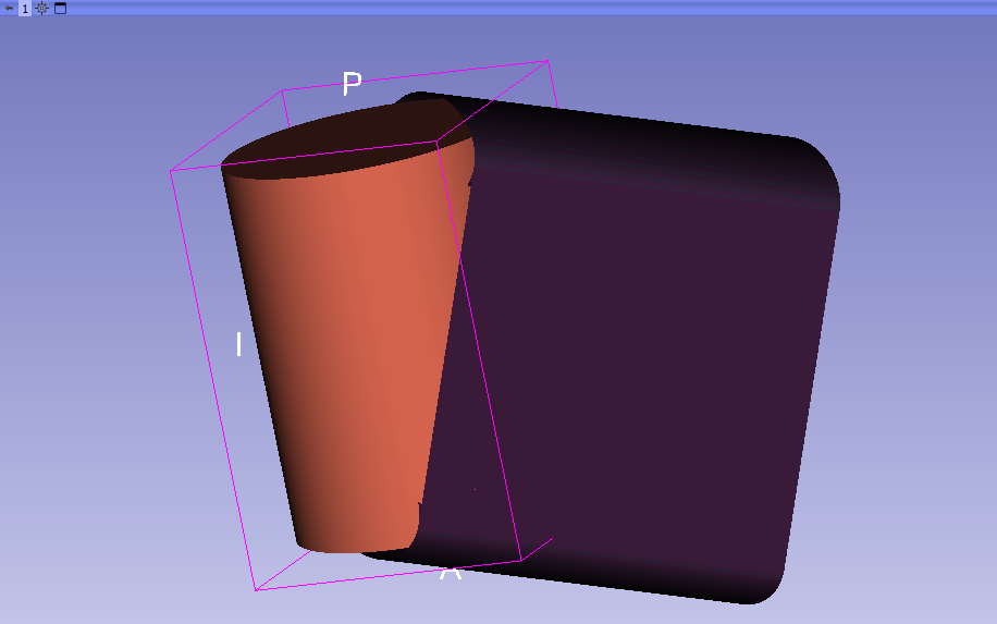
FYI- There is a concept in computational geometry called a “swept surface.” (See this article for example.) It is a powerful construct for doing things like path planning, or analyzing robot motion, in complex geometric situations. It can be used to compute bounding boxes too :slight_smile: One very fun past project was using swept surfaces to figure out how to remove an oil filter (or other parts) from a jet engine - it’s not easy to get tools in, move the tools appropriately, and get the part out. But I digress.

The basic idea is that an object is placed into a sampling volume, and then “rasterized” repeatedly, using a distance field and union set operations, as small steps are taken to move the object along its path (the path typically being a sequence of interpolated transformations) to accumulate the surface position of the object over time. . I’m sure this is way overkill for what you are trying to do, but maybe it will prompt a useful idea…

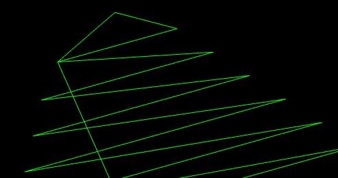
I think you could do a continous approximation of your picture example by projecting the oriented cylinder into the path normal plane and using a linear extrusion filter if your path-direction and cylinder-orientation don’t vary too frequently. I think you could use vtkCutter passing through the cylinder-center to get the projection.
Path-direction change points should be appended as cylinders.
Cylinder-orientation change (while translating or not) may be done using a rotation extrusion filter but you need to calculate some transforms to get the correct inputs for the filter.
I think you may achieve near log(n) complexity relative to your current algorithm

I don’t know if this is what Will suggests.

I have done a custom path extrusion filter for myself so I have a little bit of experience, but this post still is a mental exercise for me. Could be wrong

Hope it helps

Try myVtkTubeFilter->SidesShareVerticesOn().

regards,

Paulo

Thank you Will. You pointed me to the right filter. I need cut volume polydata, cut by a cylindrical cutter traversing along the given path of points. I don’t find this SweptSurface filter in my vtk (python). Is it still under patent rights? Any work arounds?

I created vtkImageData from the appended cylinders using vtkVoxelModeller and then used vtkMarchingCubes to extract surface. It works, but the model accuracy is not great. Here is the code:

def ConvertPolyData(self, appendedPolyData):
            
    voxel_modeller = vtk.vtkVoxelModeller()
    voxel_modeller.SetSampleDimensions(100,100,100)
    voxel_modeller.SetModelBounds(appendedPolyData.GetBounds())
    voxel_modeller.SetScalarTypeToFloat()
    voxel_modeller.SetMaximumDistance(0.1)
    voxel_modeller.SetInputData(appendedPolyData)
    voxel_modeller.Update()
    
    surface = vtk.vtkMarchingCubes()
    surface.ComputeNormalsOn()
    surface.SetInputData(voxel_modeller.GetOutput())
    iso_value = 0.1
    surface.SetValue(0, iso_value)
    surface.Update()
    
    return surface.GetOutput()

Up your sample dimensions, and use flying edges (it’s way faster especially when built threaded with TBB or STDThread).

Thanks Will. I see the impact of Flying edges. But VoxelModeller is the time killer, especially when I bump the dimensions.

vtkImplicitModeller and flying edges works way better. But still there is place to improve the final polydata accuracy.

BTW, Is there a way to remove internal cells from a polydata? These cells are coming from appending several polydatas.

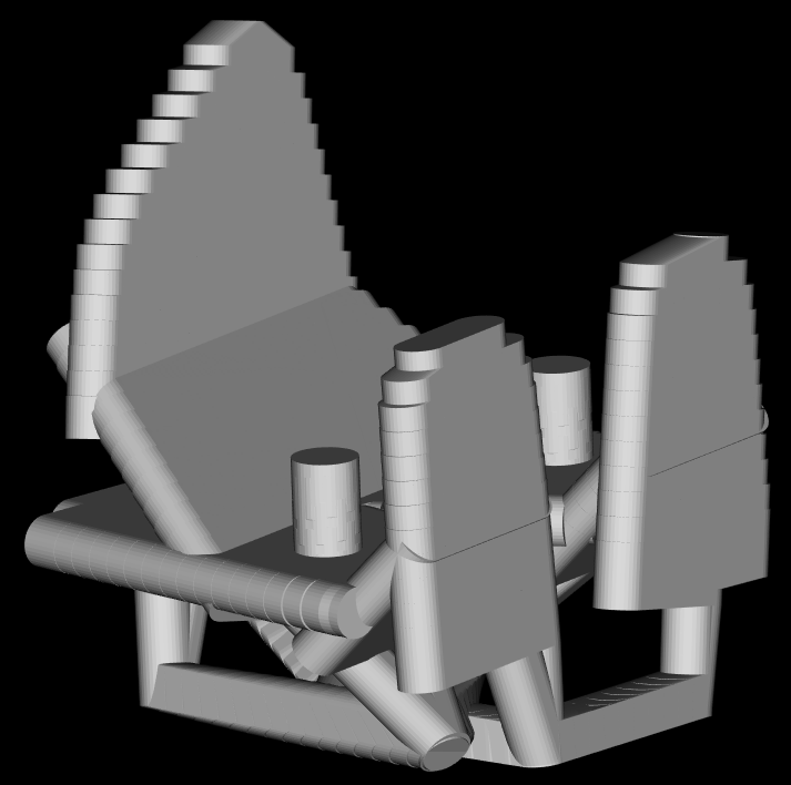
Here is same code implementing the first steps of the idea I suggested… It’s complex but I think if you put some work into it, it should work releably… The script was made to be executed on Slicer’s python interactor but you can avoid those lines and set your own mappers.

The greatest benefit of this approach is that a linear extrusion only doubles the original number of points of your original polygon, and you would do only one extrusion per uniform path direction, instead of placing n cylinders over that line

#cylinder path extrusion

import vtk

#create cylinder
cylinderSource = vtk.vtkCylinderSource()
cylinderSource.SetRadius(15)
cylinderSource.SetHeight(40)
cylinderSource.SetCenter([0,0,0])
cylinderSource.SetResolution(100)
cylinderSource.CappingOn()
cylinderSource.Update()


#add model
cylinderModel = slicer.mrmlScene.AddNewNodeByClass("vtkMRMLModelNode")
cylinderModel.SetName('cylinderModel')
cylinderModel.SetAndObservePolyData(cylinderSource.GetOutput())

import numpy as np
cylinderPathDirection = np.array([-5,3,6])/np.linalg.norm(np.array([-5,3,6]))

v1 = [0,0,0]
v2 = [0,0,0]
vtk.vtkMath.Perpendiculars(cylinderPathDirection,v1,v2,30)

rowMatrix = np.array([v1,v2])
columnMatrix = np.array([v1,v2]).T
projectionMatrix = columnMatrix @ rowMatrix

projectionMatrix4x4 = np.eye(4)
projectionMatrix4x4[:3,:3] = projectionMatrix

projectionMatrix4x4_vtk = slicer.util.vtkMatrixFromArray(projectionMatrix4x4)

finalTransform = vtk.vtkTransform()
finalTransform.PostMultiply()
finalTransform.Concatenate(projectionMatrix4x4_vtk)

transformPolyDataFilter = vtk.vtkTransformPolyDataFilter()
transformPolyDataFilter.SetInputData(cylinderSource.GetOutput())
transformPolyDataFilter.SetTransform(finalTransform)
transformPolyDataFilter.Update()

cylinderModelProjection = slicer.mrmlScene.AddNewNodeByClass("vtkMRMLModelNode")
cylinderModelProjection.SetName('cylinderModelProjection')
cylinderModelProjection.SetAndObservePolyData(transformPolyDataFilter.GetOutput())

featureEdges = vtk.vtkFeatureEdges()
featureEdges.BoundaryEdgesOn()
featureEdges.FeatureEdgesOff()
featureEdges.NonManifoldEdgesOff()
featureEdges.ManifoldEdgesOff()
featureEdges.SetInputData(transformPolyDataFilter.GetOutput())
featureEdges.Update()

cylinderModelProjectionContourCircles = slicer.mrmlScene.AddNewNodeByClass("vtkMRMLModelNode")
cylinderModelProjectionContourCircles.SetName('cylinderModelProjectionContourCircles')
cylinderModelProjectionContourCircles.SetAndObservePolyData(featureEdges.GetOutput())

featureEdges2 = vtk.vtkFeatureEdges()
featureEdges2.BoundaryEdgesOff()
featureEdges2.FeatureEdgesOn()
featureEdges2.NonManifoldEdgesOff()
featureEdges2.ManifoldEdgesOff()
featureEdges2.SetInputData(transformPolyDataFilter.GetOutput())
featureEdges2.Update()

cylinderModelProjectionContourLines = slicer.mrmlScene.AddNewNodeByClass("vtkMRMLModelNode")
cylinderModelProjectionContourLines.SetName('cylinderModelProjectionContourLines')
cylinderModelProjectionContourLines.SetAndObservePolyData(featureEdges2.GetOutput())

#polyLoops = vtk.vtkContourLoopExtraction()
#polyLoops.ScalarThresholdingOff()
#polyLoops.SetOutputModeToBoth()
#polyLoops.CleanPointsOff()
#polyLoops.SetNormal(cylinderPathDirection)
#polyLoops.SetInputData(featureEdges.GetOutput())
#polyLoops.Update()

#triangleFilter = vtk.vtkTriangleFilter()
#triangleFilter.SetInputData(featureEdges.GetOutput())
#triangleFilter.Update()

#stripperFilter = vtk.vtkStripper()
#stripperFilter.JoinContiguousSegmentsOn()
#stripperFilter.SetInputData(featureEdges.GetOutput())
#stripperFilter.Update()

#cylinderModelProjectionFace = slicer.mrmlScene.AddNewNodeByClass("vtkMRMLModelNode")
#cylinderModelProjectionFace.SetName('cylinderModelProjectionFace')
#cylinderModelProjectionFace.SetAndObservePolyData(polyLoops.GetOutput())

linearExtrusion = vtk.vtkLinearExtrusionFilter()
linearExtrusion.SetExtrusionTypeToVectorExtrusion()
linearExtrusion.SetScaleFactor(40)
linearExtrusion.SetVector(cylinderPathDirection)
linearExtrusion.SetInputData(featureEdges.GetOutput())
linearExtrusion.Update()

cylinderModelProjectionCirclesExtrusion = slicer.mrmlScene.AddNewNodeByClass("vtkMRMLModelNode")
cylinderModelProjectionCirclesExtrusion.SetName('cylinderModelProjectionCirclesExtrusion')
cylinderModelProjectionCirclesExtrusion.SetAndObservePolyData(linearExtrusion.GetOutput())

linearExtrusion2 = vtk.vtkLinearExtrusionFilter()
linearExtrusion2.SetExtrusionTypeToVectorExtrusion()
linearExtrusion2.SetScaleFactor(40)
linearExtrusion2.SetVector(cylinderPathDirection)
linearExtrusion2.SetInputData(featureEdges2.GetOutput())
linearExtrusion2.Update()

cylinderModelProjectionLinesExtrusion = slicer.mrmlScene.AddNewNodeByClass("vtkMRMLModelNode")
cylinderModelProjectionLinesExtrusion.SetName('cylinderModelProjectionLinesExtrusion')
cylinderModelProjectionLinesExtrusion.SetAndObservePolyData(linearExtrusion2.GetOutput())

Please give feedback if you think this approach have a conceptual error or you think it won’t work. Thank you

Thank you Mauro. I’m impressed with the results and the performance. Model size reduced lot.

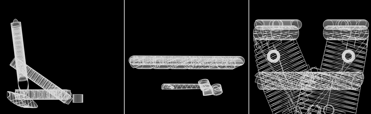
I am still appending extruded models for each line though. I need to work on deleting the points and facets inside the final appended polygon. Here is the code snippet I tried.

def ExtrudeCylinder(cylinderPolyData, scaleFactor, pathVector):

featureEdges = vtk.vtkFeatureEdges()
featureEdges.BoundaryEdgesOn()
featureEdges.FeatureEdgesOff()
featureEdges.NonManifoldEdgesOff()
featureEdges.ManifoldEdgesOff()
featureEdges.SetInputData(cylinderPolyData)
featureEdges.Update()
    
featureEdges2 = vtk.vtkFeatureEdges()
featureEdges2.BoundaryEdgesOff()
featureEdges2.FeatureEdgesOn()
featureEdges2.SetFeatureAngle(1)
featureEdges2.NonManifoldEdgesOff()
featureEdges2.ManifoldEdgesOff()
featureEdges2.SetInputData(cylinderPolyData)
featureEdges2.Update()

vtk.vtkMath.Normalize(pathVector)

linearExtrusion = vtk.vtkLinearExtrusionFilter()
linearExtrusion.SetExtrusionTypeToVectorExtrusion()
linearExtrusion.SetScaleFactor(scaleFactor)
linearExtrusion.SetVector(pathVector)
linearExtrusion.CappingOn()
linearExtrusion.SetInputData(cylinderPolyData)

linearExtrusion.SetInputData(featureEdges.GetOutput()) #This leaves the end cylinders not closed

linearExtrusion.Update()

linearExtrusion2 = vtk.vtkLinearExtrusionFilter()
linearExtrusion2.SetExtrusionTypeToVectorExtrusion()
linearExtrusion2.SetScaleFactor(scaleFactor)
linearExtrusion2.SetVector(pathVector)
linearExtrusion2.CappingOn()
linearExtrusion2.SetInputData(featureEdges2.GetOutput())
linearExtrusion2.Update()

return linearExtrusion.GetOutput(), linearExtrusion2.GetOutput()

1 Like

Hi. Glad it was useful

Can you post a picture of how the work envelope (or the result of your append filter) looks like?

Thank you

Here is the input cut path:

And here is the resultant cut volume model:

Here are the cross orthogonal sections of the model:

As you can see from the cross sections, the model is not hollow.

Congratrulations, I think you achieved your goal…

Very nice pictures!

Maybe now you can use vtkbool library to merge all the appended models into one with less points. Or you could put more work in some kind of extrusion algorithm