I often find myself in a situation where I have to deal with co-planar surfaces. The render differs depending whether or not I am using depth peeling.
Occlussion or composite change nothing in the result.
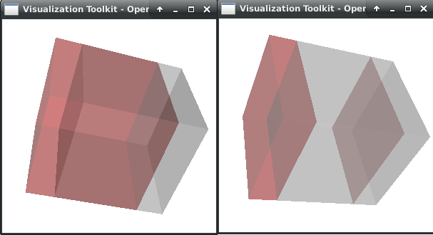
I am creating 2 cubes, that are slightly shifted in opposite directions, apply same opacity and some colors.
Left render is without depth peeling, right is with depth peeling. The central zone should be redish and it is strange that only the opposite face is colored.
I also tried VTK_USE_LEGACY_DEPTH_PEELING variable this seems to completely discard one of the cube regarding colors.
Is there any paramters I can tune in the dual depth peeling pass?
Hello,
Thank you for your answer.
Adding those settings did not change the result.
It seems that the last added block is the one rendered in the end. I was able to force the 1st cube to render on top of the second by creating another polydata instance, and using a shallowcopy. Basically I am creating a 3rd cube and discard the 1st one.
I am wondering if those block are stored in a map and thus the memory address is the thing that defines ordering (last is rendered on top).
The final pixel color is decided in the rendering pipeline in the graphics card. The decision is made by using the Z-buffer (aka depth buffer). Coplanar surfaces get the same depth values when after rastering. For this reason, they invented depth peeling, which involves the usage of two z-buffers in order to correctly render intersecting, or coplanar, translucent surfaces. Anyway, it is a low level operation that is not aware of how the original objects are in the memory space of your program. The only way to modify the behavior of the graphics pipeline is by setting flags and parameters like you did. This does not solve your problem, but hopefuly casts some light on what is going on under the hood.
As for you problem, why don’t you simply disable depth peeling? The image on the left seems to be the expected result, right?
Indeed the left image is correct for translucent cubes. But I need mapper.ScalarVisibilityOff() or I get artifacts.
So I tried deactivating the depth peeling. Sadly, if I set the opacity to 1.0, it seems the opaque pass is not done. I can force a correct render with actor.SetForceOpaque(True) but then translucent objects will have artifacts, like cells inside of them. If then I also force translucent, nothing changes, translucent render is not correct.
So I am back to depth peeling for now. I produced the screenshots below using your settings. Could you maybe try the script at the end of this post and tell me if you get the same results as those?
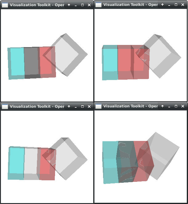
I have a blue-green cube on the left; a translated red cube in the middle with vertices overlapping the 1st cube and finally; a translated/rotated grey cube with non-overlapping vertices but co-planar fragments.
I rendered this scene with alpha blending and depth peeling. I am more interested in the cube 1 and 2 color blending than the 3rd cube artefacts
Top-left alpha blending. I assumed that each cube is rendered separately and then everything is blended together. red+(blue+green) = dark grey. So we end up with a correct blending in this case
Top-right legacy depth peeling: I guess the last inserted fragment replaces the other one. Since the 2nd cube is instanciated after the first cube, the peel will only render the 2nd cube overlapping fragments? So red only
Bottom-left dual depth peeling: I cannot make sense of this one. Front peel should be red (see above), back peel should be red too, again see above. So we should have the same render as legacy depth peeling right?
Bottom-right dual depth peeling with a little z offset for cube1. We have something similar to alpha blending but with artifacts
In the session, you will notice how I use 0.8 values for color. It looks like coplanar surfaces have their colors simply summed giving values close to 1. (light grey) instead of darkening the result.
Here is the session. You can activate depth peeling, legacy or not at the top of the file. You can apply an offset to any of the cubes.