Color does not match with values on look up table

Hello

I try to make a simple example to visualize scalar data on vtkUnstructuredGrid. The code is below

import vtk

# Create the 8-node cube (hexahedron)
points = vtk.vtkPoints()
points.InsertNextPoint(0, 0, 0)  # Node 0
points.InsertNextPoint(1, 0, 0)  # Node 1
points.InsertNextPoint(1, 1, 0)  # Node 2
points.InsertNextPoint(0, 1, 0)  # Node 3
points.InsertNextPoint(0, 0, 1)  # Node 4
points.InsertNextPoint(1, 0, 1)  # Node 5
points.InsertNextPoint(1, 1, 1)  # Node 6
points.InsertNextPoint(0, 1, 1)  # Node 7

# Create the hexahedron (cube) with 8 nodes
hexahedron = vtk.vtkHexahedron()
hexahedron.GetPointIds().SetId(0, 0)  # Node 0
hexahedron.GetPointIds().SetId(1, 1)  # Node 1
hexahedron.GetPointIds().SetId(2, 2)  # Node 2
hexahedron.GetPointIds().SetId(3, 3)  # Node 3
hexahedron.GetPointIds().SetId(4, 4)  # Node 4
hexahedron.GetPointIds().SetId(5, 5)  # Node 5
hexahedron.GetPointIds().SetId(6, 6)  # Node 6
hexahedron.GetPointIds().SetId(7, 7)  # Node 7

# Create an unstructured grid
unstructured_grid = vtk.vtkUnstructuredGrid()
unstructured_grid.SetPoints(points)
unstructured_grid.InsertNextCell(hexahedron.GetCellType(), hexahedron.GetPointIds())

# Create scalar data
scalars = vtk.vtkFloatArray()
scalars.SetName("Node Scalars")

# Assign a scalar value to each node (for illustration, values 1 to 8)
vmin = -0.3
vmax = 0.0
scalars.InsertNextValue(vmin)  # Node 0
scalars.InsertNextValue(vmin)  # Node 1
scalars.InsertNextValue(vmin)  # Node 2
scalars.InsertNextValue(vmin)  # Node 3
scalars.InsertNextValue(vmax)  # Node 4
scalars.InsertNextValue(vmax)  # Node 5
scalars.InsertNextValue(vmax)  # Node 6
scalars.InsertNextValue(vmax)  # Node 7

# Add scalar data to the unstructured grid
unstructured_grid.GetPointData().SetScalars(scalars)

# Create a lookup table for the colors
lookup_table = vtk.vtkLookupTable()
lookup_table.SetTableRange(vmin, vmax)  # Set vmin and vmax to the scalar range
lookup_table.SetNumberOfColors(256)  # Set the number of colors in the table (256 is common)
# lookup_table.SetColorSpaceToDiverging()
lookup_table.Build()  # Build the lookup table

# Create a mapper
mapper = vtk.vtkDataSetMapper()
mapper.SetInputData(unstructured_grid)
mapper.SetScalarModeToUsePointData()
mapper.SetScalarRange(vmin, vmax)
mapper.SetLookupTable(lookup_table)

# Create an actor
actor = vtk.vtkActor()
actor.SetMapper(mapper)

# Create a renderer, render window, and interactor
renderer = vtk.vtkRenderer()
renderWindow = vtk.vtkRenderWindow()
renderWindow.AddRenderer(renderer)

renderWindowInteractor = vtk.vtkRenderWindowInteractor()
renderWindowInteractor.SetRenderWindow(renderWindow)

# Add the actor to the renderer
renderer.AddActor(actor)

# Set background color to white
renderer.SetBackground(1.0, 1.0, 1.0)

# Use the scalar bar to display the color range
scalarBar = vtk.vtkScalarBarActor()
scalarBar.SetLookupTable(lookup_table)
scalarBar.SetTitle("Node Scalars")
scalarBar.SetNumberOfLabels(5)

# Add the scalar bar to the renderer
renderer.AddActor2D(scalarBar)

# # Create an axes actor (this will be used for vtkOrientationMarkerWidget)
# axes = vtk.vtkAxesActor()

# # Create the orientation marker widget
# orientation_marker = vtk.vtkOrientationMarkerWidget()
# orientation_marker.SetOrientationMarker(axes)
# orientation_marker.SetInteractor(renderWindowInteractor)
# orientation_marker.SetViewport(0.0, 0.0, 0.2, 0.2)  # Position of the axes in the viewport (relative coordinates)
# orientation_marker.SetEnabled(True)  # Enable the widget

# Set the camera position
camera = renderer.GetActiveCamera()
camera.SetPosition(3, 3, 3)  # Position the camera at (3, 3, 3)
camera.SetFocalPoint(0.5, 0.5, 0.5)  # Set the focal point (where the camera looks)
camera.SetViewUp(0, 1, 0)  # Set the view-up direction

# Set the size of the render window
renderWindow.SetSize(600, 600)

# Start the rendering loop
renderWindow.Render()

# style = vtk.vtkInteractorStyleTrackballCamera()
# renderWindowInteractor.SetInteractorStyle(style)
renderWindowInteractor.Start()

In this setup the top is set with max value and bottom with min value, so in principal the color on the cube should match with the scalar bar, but it seem not to be the case. Does anyone have idea which is missing in this setup to have correct color mapping?
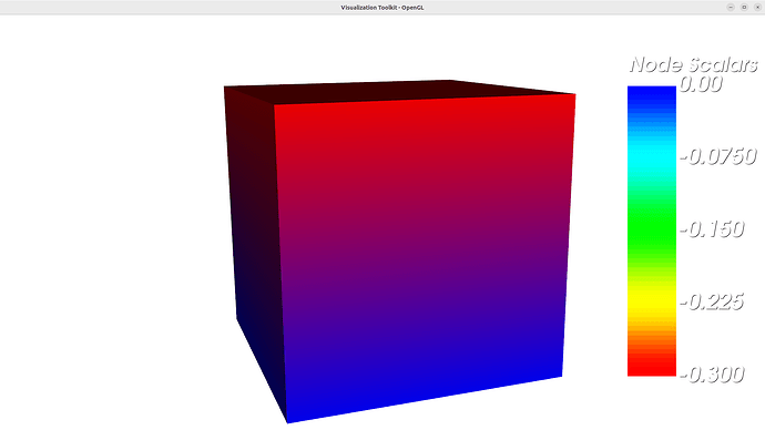
I found the reason. The color is computed only at the vertices and then interpolated linearly over cell, without using the LUT. Is there a flag to change this behavior?

Calling vtkMapper::InterpolateScalarsBeforeMappingOn() on your mapper should do this.

Thanks. You saved my day.

I also noticed that InterpolateScalarsBeforeMappingOn on works with scalar field , not vector field. In the new code below I set the vector values to the node and activate the correct component by using SelectColorArray and SetArrayComponent, but only field 0 is visualized correctly

import vtk

# Create the 8-node cube (hexahedron)
points = vtk.vtkPoints()
points.InsertNextPoint(0, 0, 0)  # Node 0
points.InsertNextPoint(1, 0, 0)  # Node 1
points.InsertNextPoint(1, 1, 0)  # Node 2
points.InsertNextPoint(0, 1, 0)  # Node 3
points.InsertNextPoint(0, 0, 1)  # Node 4
points.InsertNextPoint(1, 0, 1)  # Node 5
points.InsertNextPoint(1, 1, 1)  # Node 6
points.InsertNextPoint(0, 1, 1)  # Node 7

# Create the hexahedron (cube) with 8 nodes
# hexahedron = vtk.vtkHexahedron()
hexahedron = vtk.vtkLagrangeHexahedron()
hexahedron.GetPointIds().SetId(0, 0)  # Node 0
hexahedron.GetPointIds().SetId(1, 1)  # Node 1
hexahedron.GetPointIds().SetId(2, 2)  # Node 2
hexahedron.GetPointIds().SetId(3, 3)  # Node 3
hexahedron.GetPointIds().SetId(4, 4)  # Node 4
hexahedron.GetPointIds().SetId(5, 5)  # Node 5
hexahedron.GetPointIds().SetId(6, 6)  # Node 6
hexahedron.GetPointIds().SetId(7, 7)  # Node 7

# Create an unstructured grid
unstructured_grid = vtk.vtkUnstructuredGrid()
unstructured_grid.SetPoints(points)
unstructured_grid.InsertNextCell(hexahedron.GetCellType(), hexahedron.GetPointIds())

# Create scalar data
pointDataArray = vtk.vtkFloatArray()
pointDataArray.SetName("Nodal_displacements")
pointDataArray.SetNumberOfComponents(3)
pointDataArray.InsertNextTuple3(0.0, 0.0, 0.0)      # Node 0
pointDataArray.InsertNextTuple3(0.1, 0.0, 0.0)      # Node 1
pointDataArray.InsertNextTuple3(0.1, -0.03, 0.0)     # Node 2
pointDataArray.InsertNextTuple3(0.0, -0.03, 0.0)    # Node 3
pointDataArray.InsertNextTuple3(0.0, 0.0, -0.03)    # Node 4
pointDataArray.InsertNextTuple3(0.1, 0.0, -0.03)    # Node 5
pointDataArray.InsertNextTuple3(0.1, -0.03, -0.03)  # Node 6
pointDataArray.InsertNextTuple3(0.0, -0.03, -0.03)  # Node 7

# Add scalar data to the unstructured grid
unstructured_grid.GetPointData().AddArray(pointDataArray)

# Create a lookup table for the colors
vmin = -0.03
vmax = 0.0
lookup_table = vtk.vtkLookupTable()
lookup_table.SetTableRange(vmin, vmax)  # Set vmin and vmax to the scalar range
lookup_table.SetNumberOfColors(256)  # Set the number of colors in the table (256 is common)
# lookup_table.SetColorSpaceToDiverging()
lookup_table.Build()  # Build the lookup table

# Create a mapper
mapper = vtk.vtkDataSetMapper()
mapper.SetInputData(unstructured_grid)
mapper.ScalarVisibilityOn()
mapper.SetScalarModeToUsePointFieldData()
mapper.SelectColorArray("Nodal_displacements")
mapper.SetArrayComponent(1)
mapper.SetScalarRange(vmin, vmax)
mapper.SetLookupTable(lookup_table)
mapper.InterpolateScalarsBeforeMappingOn() # important to let the cell to interpolate the scalar before doing color mapping
# otherwise the color will be interpolated via vertex value and it will not be accurate
# Ref: https://discourse.vtk.org/t/color-does-not-match-with-values-on-look-up-table/15459

# Create an actor
actor = vtk.vtkActor()
actor.SetMapper(mapper)

# Create a renderer, render window, and interactor
renderer = vtk.vtkRenderer()
renderWindow = vtk.vtkRenderWindow()
renderWindow.AddRenderer(renderer)

renderWindowInteractor = vtk.vtkRenderWindowInteractor()
renderWindowInteractor.SetRenderWindow(renderWindow)

# Add the actor to the renderer
renderer.AddActor(actor)

# Set background color to white
renderer.SetBackground(1.0, 1.0, 1.0)

# Use the scalar bar to display the color range
scalarBar = vtk.vtkScalarBarActor()
scalarBar.SetLookupTable(lookup_table)
# scalarBar.SetTitle("Node Scalars")
scalarBar.SetNumberOfLabels(5)

# Add the scalar bar to the renderer
renderer.AddActor2D(scalarBar)

# # Create an axes actor (this will be used for vtkOrientationMarkerWidget)
# axes = vtk.vtkAxesActor()

# # Create the orientation marker widget
# orientation_marker = vtk.vtkOrientationMarkerWidget()
# orientation_marker.SetOrientationMarker(axes)
# orientation_marker.SetInteractor(renderWindowInteractor)
# orientation_marker.SetViewport(0.0, 0.0, 0.2, 0.2)  # Position of the axes in the viewport (relative coordinates)
# orientation_marker.SetEnabled(True)  # Enable the widget

# Set the camera position
camera = renderer.GetActiveCamera()
camera.SetPosition(3, 3, 3)  # Position the camera at (3, 3, 3)
camera.SetFocalPoint(0.5, 0.5, 0.5)  # Set the focal point (where the camera looks)
camera.SetViewUp(0, 1, 0)  # Set the view-up direction

# Set the size of the render window
renderWindow.SetSize(600, 600)

# Start the rendering loop
renderWindow.Render()

# style = vtk.vtkInteractorStyleTrackballCamera()
# renderWindowInteractor.SetInteractorStyle(style)
renderWindowInteractor.Start()