The examples for constraining a vtkDelaunay2D all show how to essentially punch a hole out of the generated mesh.
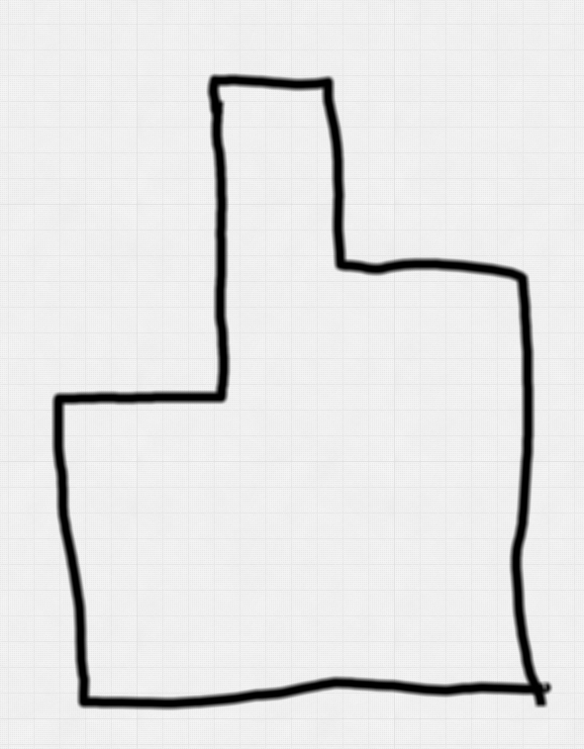
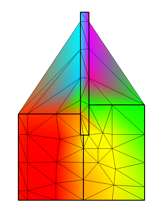
However, I’m not sure how to constrain the surface plot my vtkDelaunay2D comes up with to a “positive” shape…essentially making sure the generated mesh doesn’t extend past the edges of the blocky cross section of my frame (as shown above).
The thin black lines show the generated mesh (via the EdgeVisibilityOn method).
The thick black lines are a separate plot showing the polygon “cells” of my frame. It’s not part of the delaunay plot but I’m showing them here just to help make the basic shape of the frame visible.
For the delaunay surface plot, I’m just using all the points in the entire window frame shape and then the “boundary” points from the outside edge all the way around, like so:
# Create source points for the window frame
points = vtk.vtkPoints()
for index, t_node in enumerate(self._construction_model.t_nodes):
    t_node.vtk_id = points.InsertNextPoint(t_node.x, t_node.y, 0.0)

# Add points to polydata
polydata = vtk.vtkPolyData()
polydata.SetPoints(points)

# Create a boundary containing the subset of points
# describing the boundary of the window frame
boundary_poly = vtk.vtkPolygon()
boundary_cell_array = vtk.vtkCellArray()
# The t_node objects in t_boundary are the same as those in t_nodes
# so vtk_id has already been set above and we can use here.
for index, t_node in enumerate(self._construction_model.t_boundary):
    boundary_poly.GetPointIds().InsertNextId(t_node.vtk_id)

boundary_polydata.SetPoints(polydata.GetPoints())
boundary_cell_array.InsertNextCell(boundary_poly)
boundary_polydata.SetPolys(boundary_cell_array)

delaunay = vtk.vtkDelaunay2D()
delaunay.SetInputData(polydata)
delaunay.SetSourceData(boundary_polydata)
delaunay.Update()
delaunay_output = delaunay.GetOutput()
Any thoughts on how to get the colored plot to stay inside the boundary that describes the edges of my cross section?
Still trying to grok basics of VTK so the answer to this might be obvious. Apologies if so.
We do this very similarly in 3D Slicer and it works well. What you might miss is inversion of the polygon to ensure that it has correct winding (points must be listed in clockwise order). Another difference is that we use the same polydata as source and input (I don’t know if it matters).
You may try to change invert the winding of the polygon (CW/CCW). If that does not work then you can try to find an example or test that is similar to what you need to do and check if that works and what’s the difference compared to your code.
Thanks @lassoan. Funny thing is, I can’t seem to find an example where the mesh is constrained to the inside of some polygon. All the existing examples are to show how to punch a hole out of the mesh.
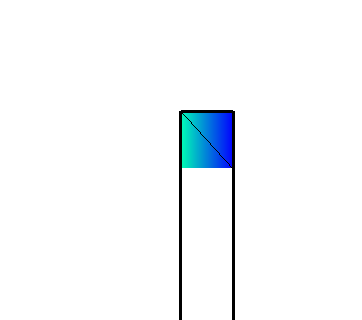
When I reverse the order of the points I get only slightly better. Just the top of the glass part of the model shows:
I do see in my log output a warning which may be somehow involved:
Warning: In /Users/prabhu/src/git/VTKPythonPackage/standalone-build/VTK-source/Filters/Core/vtkDelaunay2D.cxx, line 1357
vtkDelaunay2D (0x7fc3b8733620): Edge not recovered, polygon fill suspect
@danielmcquillen, can you share a csv (or vtk) file of the input nodes? I have a few ideas on how this can be achieved but I want to test it with this example geometry
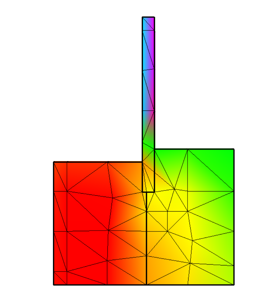
Aha! Thanks @lassoan and @banesullivan for your help, but I figured out the issue. My boundary definition was optimized and didn’t include every node on the boundary, which turned out to be the problem. I had to include every node that happened to be on the boundary in order to allow the delaunay algo to generate correctly, which in hindsight seems so obvious. (Sigh. Not the first time I’m smacking my forehead…and I’m sure not the last.)