Could VTK be used to re-construct colorful 3D using colorful CT images?

Hi,

There are 300 colorful CT slice images. Could I use VTK to re-construct colorful 3D using those colorful CT images? Is there any example code for my reference?

Thanks and Best Regards,
Ardeal

Yes, VTK can render beautiful 4D (3D + color) RGB volumes. You can use any of the volume rendering examples, in the volume property set scalar opacity transfer function as usual, but instead of setting a color transfer function, set IndependentComponents to False. See this example:

If you want to use a GUI to set up volume rendering then you can use 3D Slicer as explained in this post:

Hi,
Many thanks for your reply!
Is there any complete example about the 4D(3D + color) volumes?
I am sorry that I am not good at VTK, especially not good at 4D using VTK.

There are a number of tests that shows how IndependentComponents=false can be used. If you create a small standalone example then it would be great if you could contribute to the VTK examples site.

Since you work with CT images, it could make sense to use VTK in Slicer’s Python environment, because then you can get nice volume rendering using a few lines of Python code and/or set it up or adjust parameters using interactive GUI (if you need help using Slicer then post on the Slicer forum).

Hi,

I could run 3D reconstruction, and my test code is on github:https://github.com/ardeal/vtk_4d_ct.
The upper code only works on 3D.

I am very glad to contribute to VTK examples site. However the upper code doesn’t work on 4D.
Could you help to tell me how to change the upper code to make it work on 4D(colorful CT slice images)?

Once it work, I will upload it to VTK examples site.

Thanks and Best Regards,
Ardeal

  1. The single most-important thing for rendering RGB volumes is to set IndependentComponents to false. You don’t set that in your code.

  2. Probably it is theoretically possible to save 3D RGB color volume in DICOM format but such images would be extremely rare. What software did produce the RGB volume (the “300 colorful CT slice images”)? What image format it is stored in?

I don’t know where to set IndependentComponents = flase. Could you help to change the code directly?

I use the CT to generate gray images which are then used to generate colorful images. The generated images are dicom format. I could read and display the colorful dicom images using pydicom successfully.

By the way, if Slicer you mentioned works for my colorful images, I am willing to try it. however I could not access it. Perhaps, there is something wrong with my network.

The following image is the dicom file plotted in pydicom:
image

This looks like a plain scalar volume displayed with a color look-up-table. Since this is not a vector volume (a voxel is not RGB triplet but a simple scalar value), you can use any VTK medical volume rendering examples, as is, without disabling IndependentComponents. You can set up the blue-green-red coloring in the color transfer function.

Hi,
No matter what the dicom file is, I would like to know how to set IndependentComponents=false.
in my code: https://github.com/ardeal/vtk_4d_ct, Could you tell me where and how to set this property?

I pasted the code as follows:

int main(int argc, char *argv[])

{

const char * dirname = "D:\\aaa\\dicom\\1data\\PA0\\ST0\\SE1";

int clip = 0;

//------------------------------- Read DICOM images
vtkSmartPointer<vtkAlgorithm> reader = vtkSmartPointer<vtkAlgorithm>::New();
vtkSmartPointer<vtkImageData> input = vtkSmartPointer<vtkImageData>::New();
vtkSmartPointer<vtkDICOMImageReader> dicomReader = vtkSmartPointer<vtkDICOMImageReader>::New();
dicomReader->SetDirectoryName(dirname);
dicomReader->Update();
input = dicomReader->GetOutput();
reader = dicomReader;

//------------------------------- Set the colors.
vtkSmartPointer<vtkNamedColors> colors = vtkSmartPointer<vtkNamedColors>::New();
std::array<unsigned char, 4> skinColor{ { 255, 125, 64 } };
colors->SetColor("SkinColor", skinColor.data());
std::array<unsigned char, 4> bkg{ { 51, 77, 102, 255 } };
colors->SetColor("BkgColor", bkg.data());

//------------------------------- Skin 
// An isosurface, or contour value of 500 is known to correspond to the skin of the patient.
// The triangle stripper is used to create triangle strips from the isosurface; these render much faster on many systems.
vtkSmartPointer<vtkMarchingCubes> skinExtractor = vtkSmartPointer<vtkMarchingCubes>::New();
skinExtractor->SetInputConnection(reader->GetOutputPort());
skinExtractor->SetValue(0, 100);

vtkSmartPointer<vtkStripper> skinStripper = vtkSmartPointer<vtkStripper>::New();
skinStripper->SetInputConnection(skinExtractor->GetOutputPort());

vtkSmartPointer<vtkPolyDataMapper> skinMapper = vtkSmartPointer<vtkPolyDataMapper>::New();
skinMapper->SetInputConnection(skinStripper->GetOutputPort());
skinMapper->ScalarVisibilityOff();

vtkSmartPointer<vtkActor> skin = vtkSmartPointer<vtkActor>::New();
skin->SetMapper(skinMapper);
skin->GetProperty()->SetDiffuseColor(colors->GetColor3d("SkinColor").GetData());
skin->GetProperty()->SetSpecular(.3);
skin->GetProperty()->SetSpecularPower(20);
skin->GetProperty()->SetOpacity(.5);

#if 1
//------------------------------- Bone
// An isosurface, or contour value of 1150 is known to correspond to the bone of the patient.
// The triangle stripper is used to create triangle strips from the isosurface; these render much faster on may systems.
vtkSmartPointer boneExtractor = vtkSmartPointer::New();
boneExtractor->SetInputConnection(reader->GetOutputPort());
boneExtractor->SetValue(0, 300);

vtkSmartPointer<vtkStripper> boneStripper = vtkSmartPointer<vtkStripper>::New();
boneStripper->SetInputConnection(boneExtractor->GetOutputPort());

vtkSmartPointer<vtkPolyDataMapper> boneMapper = vtkSmartPointer<vtkPolyDataMapper>::New();
boneMapper->SetInputConnection(boneStripper->GetOutputPort());
boneMapper->ScalarVisibilityOff();

vtkSmartPointer<vtkActor> bone = vtkSmartPointer<vtkActor>::New();
bone->SetMapper(boneMapper);
bone->GetProperty()->SetDiffuseColor(colors->GetColor3d("Ivory").GetData());

#endif

//------------------------------- Outline // An outline provides context around the data.
vtkSmartPointer<vtkOutlineFilter> outlineData = vtkSmartPointer<vtkOutlineFilter>::New();
outlineData->SetInputConnection(reader->GetOutputPort());

vtkSmartPointer<vtkPolyDataMapper> mapOutline = vtkSmartPointer<vtkPolyDataMapper>::New();
mapOutline->SetInputConnection(outlineData->GetOutputPort());

vtkSmartPointer<vtkActor> outline = vtkSmartPointer<vtkActor>::New();
outline->SetMapper(mapOutline);
outline->GetProperty()->SetColor(colors->GetColor3d("Black").GetData());

//------------------------------- camera
// It is convenient to create an initial view of the data. The FocalPoint and Position form a vector direction. Later on (ResetCamera() method)
// this vector is used to position the camera to look at the data in this direction.
vtkSmartPointer<vtkCamera> aCamera = vtkSmartPointer<vtkCamera>::New();
aCamera->SetViewUp(0, 0, -1);
aCamera->SetPosition(0, -1, 0);
aCamera->SetFocalPoint(0, 0, 0);
aCamera->ComputeViewPlaneNormal();
aCamera->Azimuth(30.0);
aCamera->Elevation(30.0);

//------------------------------- create winwow
// Create the renderer, the render window, and the interactor. 
// The renderer draws into the render window, the interactor enables mouse- and keyboard-based interaction with the data within the render window.
vtkSmartPointer<vtkRenderer> aRenderer = vtkSmartPointer<vtkRenderer>::New();
vtkSmartPointer<vtkRenderWindow> renWin = vtkSmartPointer<vtkRenderWindow>::New();
renWin->AddRenderer(aRenderer);
vtkSmartPointer<vtkRenderWindowInteractor> iren = vtkSmartPointer<vtkRenderWindowInteractor>::New();
iren->SetRenderWindow(renWin);


//------------------------------- display
// Actors are added to the renderer. An initial camera view is created. The Dolly() method moves the camera towards the FocalPoint, thereby enlarging the image.
//aRenderer->AddActor(outline);
//aRenderer->AddActor(skin);
aRenderer->AddActor(bone);
aRenderer->SetActiveCamera(aCamera);
aRenderer->ResetCamera();
aCamera->Dolly(1.5);

// Set a background color for the renderer and set the size of the render window (expressed in pixels).
aRenderer->SetBackground(colors->GetColor3d("BkgColor").GetData());
renWin->SetSize(640, 480);

// Note that when camera movement occurs (as it does in the Dolly() method), the clipping planes often need adjusting. Clipping planes consist of two planes: near and far along the view direction.
// The near plane clips out objects in front of the plane; the far plane clips out objects behind the plane. This way only what is drawn between the planes is actually rendered.
aRenderer->ResetCameraClippingRange();

// Initialize the event loop and then start it.
renWin->Render();
iren->Initialize();
iren->Start();

return EXIT_SUCCESS;

}

IndependentComponents can be enabled/disabled in volume property object.

In my code, there isn’t such a property.
the objects defined in my code are:

vtkSmartPointer<vtkMarchingCubes> skinExtractor = vtkSmartPointer<vtkMarchingCubes>::New();
vtkSmartPointer<vtkStripper> skinStripper = vtkSmartPointer<vtkStripper>::New();
vtkSmartPointer<vtkPolyDataMapper> skinMapper = vtkSmartPointer<vtkPolyDataMapper>::New();
vtkSmartPointer<vtkActor> skin = vtkSmartPointer<vtkActor>::New();

Which should have this property?

We have tried to volume render CT scans or DICOM files by going directly to numpy arrays and using pyvista. pyvista is python wrappings on top of C++ of VTK. Long term I think its better just learn C++ and make it work but for prototyping its possibly to accomplish.

image

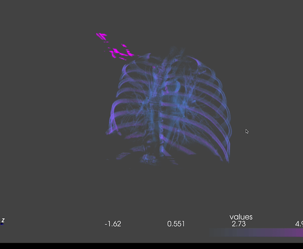
We have had success but there is still a lot of development required, I think to make the conversion of CT scans to 3D objects.

def displayer(numpy_mask):
  data_matrix = numpy_mask
  opacity = [0, 0, 0, 4, 8, 0, 0] 
  data = pv.wrap(data_matrix)

  pv.set_plot_theme("night")
  #print(type(data)) #pyvista.core.grid.UniformGrid'
  #print(dir(data)) #x = pickle.dumps(data) #print(x)
  #print(BytesIO(data))
  return data

if you ever want to talk lesliemwubbel@gmail.com

Hi,
I don’t understand what you mean. I would like to re-construct 4D using colorful CT slice images. Do you mean that VTK doesn’t support re-construct 4D using colorful CT slice images?

You are going to re-construct 4D using the pyvista which is on the top of C++ of VTK. is my understanding correct?

yes what I am saying is it’s possible to create a 4D color CT slice images. like you can totally do it but I was recommending pyvista maybe could be a solution to get what you want.

to your question yes that is what I am saying