DICOM orientation handling

Apologies for yet another DICOM handling question but couldn’t seem to find the answer to my question.

We need to integrate VTK into our existing application which has it own custom loading of the DICOM data, so using vtk-dicom or similar is not an option. I did try vtkDICOMImageReader in my test application just for comparison … while the results were not exactly the same, it had very similar issues.

In my own loader, I am populating the vtkImageData buffer by directly copying in the DICOM pixel data. Note that even though DICOM pixel data is oriented top left, I thought that correctly setting the direction matrix based on the DICOM orientation vectors would allow ensure proper handling even though VTK’s default is +Y pointing upwards (is this a correct assumption?) For example, I used a standard axial dataset that has the identity matrix (which I specify as the vtkImageData direction matrix). Also note, I am loading the lowest slices first in the buffer … which matches with the z direction in the identity matrix specified.

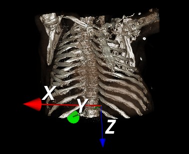
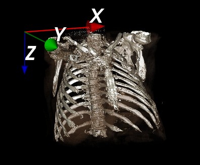
Now the issue is when I go to display this data, the orientation (and image) seems messed up. I have a simple volume rendering pipeline and I want an initial coronal view of the image from the anterior direction. To achieve this I set my camera position to a large -Y value. However, in order to get the head (+z in DICOM) at the top of the image, I needed to use a ViewUp vector of (0,0,-1) which makes no sense to me. In DICOM, the head should be +z, not -z. Also note that the image appears flipped in the lateral direction … the person’s right side is on the +x axis and it should be on the -x axis.

I then tried the vtkDICOMImageReader for comparison. It also still required a ViewUp vector of (0,0,-1). The lateral direction is now OK, but the anterior/posterior direction is now messed up. I took a quick look at the code and I see they flip the order of the pixel data rows (bottom row to the top) which I think explains what I visually see. I don’t understand why they still keep the same identity matrix even though it is flipping the row data … seems to me they should have changed that since they changed the order of the rows in the pixel data.

I am really hoping someone can shed some light on this or point me to an informative post that explains exactly the relationship between vtkImageData, the direction matrix, and how it gets interpreted by vtk.

The vtkDICOMImageReader flips the ordering of the rows for historical reasons: when in was written, the only way to display 2D images in VTK was via the vtkImageMapper, which assumes bottom-to-top ordering. And the vtkDICOMImageReader really hasn’t changed much since its original implementation 22 years ago, it really hasn’t kept up with the rest of VTK. The vtkDICOMImageReader ignores the image orientation matrix completely, which is why it’s always identity.

But if you create the vtkImageData yourself and set the orientation matrix correctly, then the volume rendering orientation should also be correct. Unlike the vtkDICOMImageReader, the vtkVolume/vtkVolumeMapper classes understand and apply the orientation.

One thing you have to watch for is how the slices in the DICOM are stacked. Let’s take a stack of axial slices as an example, where the first slice is at the superior end. If these are directly stored in the vtkImageData, then z-index = 0 is at the top, z-index = 1 is one z-spacing below that, etc. so the z-vector provided by the orientation matrix needs to be negative. So in this situation, the image orientation matrix would be:

/ 1  0  0 \
| 0  1  0 |
\ 0  0 -1 /

If the slices are stacked inferior-to-superior, however, the matrix for axial images is simply identity.

So when building the orientation matrix, the slice ordering needs to be taken into account. The first two columns of the matrix are always from the ImageOrientationPatient, and then the third column is either the cross product or the negative cross product of the first two columns.

In such situations it’s also possible to avoid using a negative cross product by reversing the ordering of the slices when building the image data, this requires using the ImagePositionPatient of the last slice rather than of the first slice.

Edit: At about the same time that I wrote vtk-dicom, I wrote a document called ImageOrientation.pdf about orienting DICOM in VTK. It’s outdated (from before vtkImageData had a Direction matrix) and it’s rough around the edges, but some of it is still relevant.

Thanks for the quick feedback. For my simple test case, the slices were in fact being stacked in a superior → inferior order. Stacking them inferior → superior does indeed fix the problem. I was thrown off track because when I tried using the vtkDICOMImageReader, it had the same issue about the direction of Z but I assumed it was correctly loading the images in the right order. I see now there is an ‘ascending’ flag in that reader code, but I didn’t see it getting set to true.

If I may ask you another DICOM loading question … what is the proper way to deal with rescale slope and intercept. Again I saw in the vtkDICOMImageReader that it is actually changing each pixel value in the volume data to account for those values … I am really hoping there is a newer way to deal with them instead of having to change each pixel value in the data?

It has always been possible to deal with the Rescale by adjusting the TableRange of the vtkLookupTable, if you’re using a lookup table, or by adjusting the positions of the control points in the color transfer function and opacity transfer function, if you’re doing volume rendering.

In DICOM terms, this is equivalent combining the Modality LUT and VOI LUT into one single step. Let’s say your VOI LUT goes from -1000 HU to +2200 HU. And the RescaleSlope is 1 and the RescaleIntercept is -1024. To convert from modality values (i.e. HU) to stored PixelData values, subtract the RescaleIntercept from the HU and then divide by the Rescale Slope. Therefore a window of [-1000,2200] HU becomes [24,3224] for the raw PixelData, and you can use LookupTable->SetTableRange(24,3224) to make your lookup table do the Modality LUT and VOI LUT in one single operation.

For color/opacity transfer functions, the idea is similar: reposition all the control points by taking their positions in HU, and then subtracting the RescaleIntercept and dividing by the RescaleSlope to get their new positions.

The only times when this doesn’t work is when working with PET images, which have a different RescaleSlope for each slice, or the occasional CT that uses different RescaleIntercept for different slices.