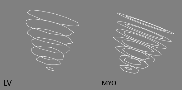
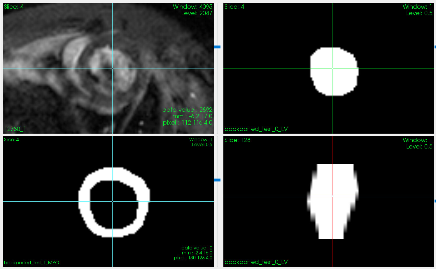
Hey everyone, in my resent campaign to create binary masks I’ve run into an issue that I’m unsure how to troubleshoot. I’m able to visualize the contours i want to create but when i export them, the images are wrong (I’m still using this filter for that). The contours in question (preclinical heart CMR):
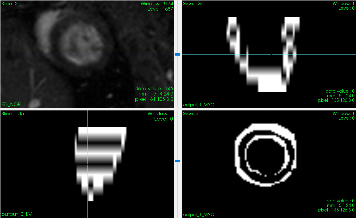
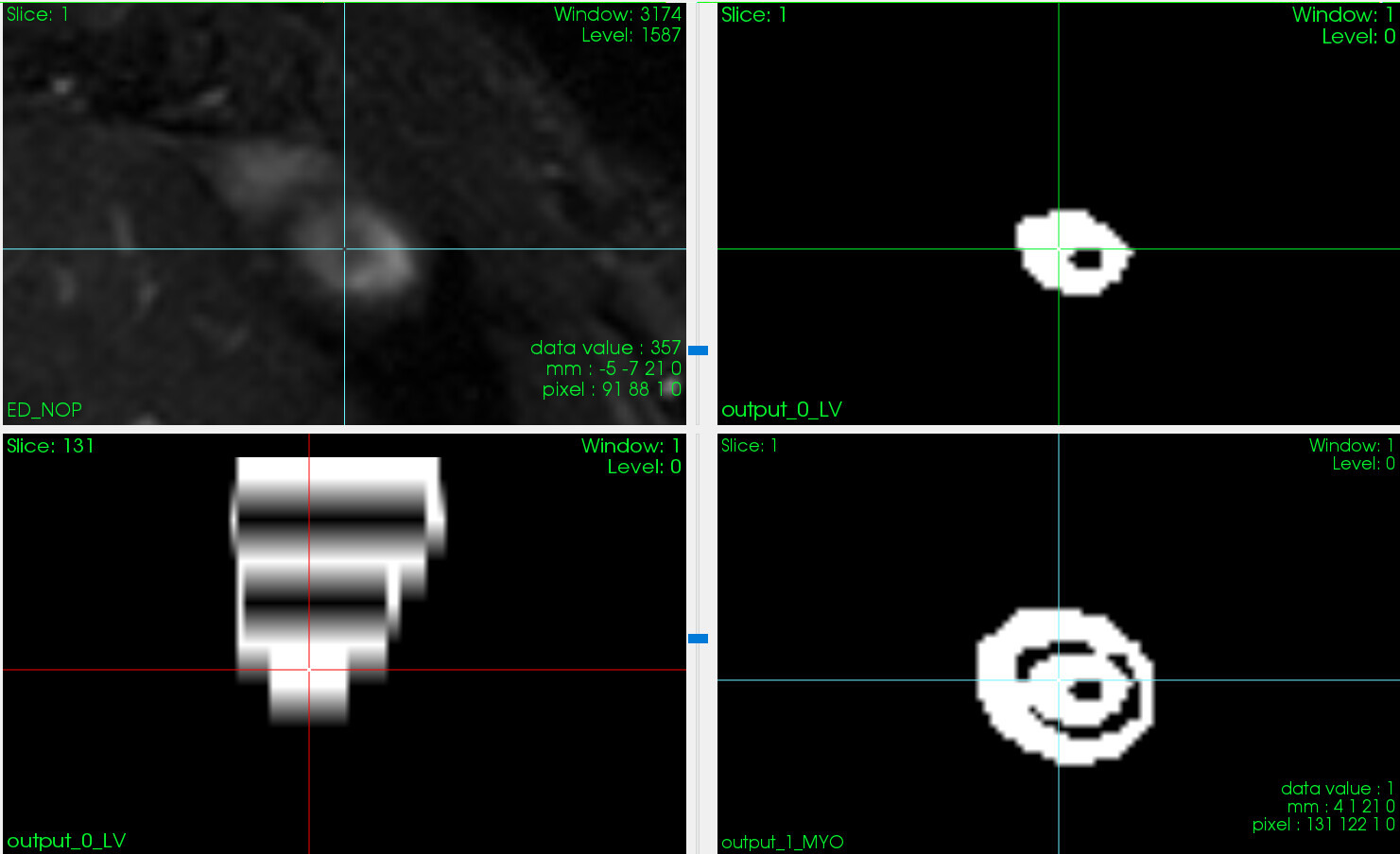
My problem is that when I’m exporting the final binarized images, I’m getting weird differentiation of the adjacent Z slices. Like so:
This seems to happen at every other frame along the Z axis.
I’m fairly sure that the problem is something simple but I’m unsure on how to troubleshoot this, since i can verify the data passed are correct (2D polydata stacking with the append filter, coordinates also look fine). My supervisor suggested that the issue lies within the ordering of the points although i went through the process of ordering them (cw & ccw) to no avail.
Any input on how to navigate problems like these is appreciated.
First of all, avoid using DICOM RTSTRUCT. It was developed decades ago when images were still manually contoured in 2D and high-resolution voxel-based segmentation representations were computationally challenging. Even then, it only barely fulfilled the needs of some radiation treatment planning tasks and never intended to be a general-purpose representation of 3D shape. It is a terribly bad format for representing 3D region of interests for many reasons (there are a lot of uncertainty about where a contour should end and what should be the end cap shape, how to deal with branching, holes, etc.) People who still need to interface with radiation treatment planning systems that only supports RTSTRUCT input/output may need to bite the bullet and struggle with this segmentation representation, but everyone else should stay away.
If you absolutely have no other way around and need to convert planar contours to closed surface or binary labelmap then you need to carefully choose what method you use. Naïve algorithms based on slice-by-slice polygon to binary labelmap conversion (such as the one in clitkDicomRTStruct2ImageFilter) perform acceptably only for simple blob-like shapes and they are expected to fail as you showed in the screenshots above for non-trivial shapes. If you need to deal with more complex shapes (thin structures, branching, etc.) then you can try SlicerRT extension of 3D Slicer. Note that SlicerRT implements the DICOM standard way of specifying holes in contours using the keyhole technique (polygon winding is ignored, you need to connect the outer contour to the inner contour with a thin “handle”; see the DICOM standard for details). Couple of years ago, the DICOM standard was amended to allow specifying that polygon winding indicates holes, but I’m not sure how widely this is supported in current RTSTRUCT implementations.
How did you create these parallel contours? Could you simply create a binary segmentation instead?
To segment the myocardium, it may be better to create two overlapping segments - one for the whole heart (outer surface of the myocardium, no holes in it) and another segment for the contrast agent. This way you don’t need to deal with thin structures, which can be challenging (depending on the resolution, topology may change etc.). Segmenting the contrast agent in each ventricle and atrium is also useful when you need to segment not just the left ventricle but also the right ventricle, septum, etc. because then all segments you need can be derived by simple label image processing operations.
You can post cardiac imaging related questions to the 3D Slicer forum to reach a large open-source developer community with lots experience in segmenting cardiac structures in ultrasound, CT, MRI and use it for quantitative analysis, surgical planning, device placement simulation, etc.
@sankhesh They aren’t exactly artifacts, what is happening is that the Z planes decide to intersect on another. Like in the second screenshot you can see the top right LV contour having the myo contour from slice 0, this also appends itself to the myo contour.
@lassoan i totally agree that I’m dealing with a dinosaur (quite literally this piece of code is almost as old as me!). I feel i should have given a little bit of context, but i skipped it as to not write a small book.
The contours were created via a shareware we no longer have license for and the contours were saved in a form of nested dictionary. There’s a file for each spatial slice of the heart; each of them has two images, one for the diastolic and one for the systolic phase. There was no protocol when these were created so information like which one is which is nowhere to be found. The only thing contained within these were the x,y coordinates and the color code the tool was using to draw the lines. I followed a naive assumption that diastolic will always have bigger surface from the systolic phase and went with that to create json files for each patient. If code is of any interest to you i made a gist for it here. The json files I created were a unification of all the files for a patient in the diastolic & systolic phase. This gives a nested object of: tissue type → spatial slice → coordinates .
I then wrote some code in C++ (here) to read the jsons i created within the tool i was asked to extend and then made the necessary modification to the RTStructFilter to pass the same mesh that it was getting via the RTContour to it.
All in all i don’t think I’m dealing with a complex structure. But there is definitely something wrong in the way I’m implementing this, my problem is that I’ve been looking over it for days and I can’t figure out.
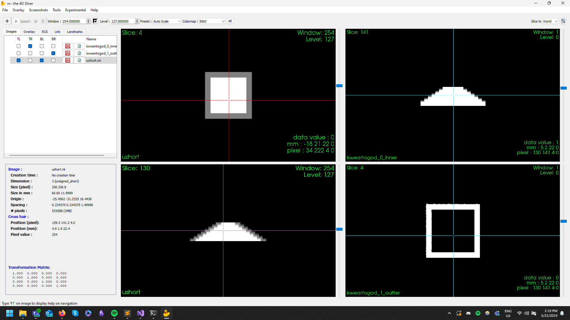
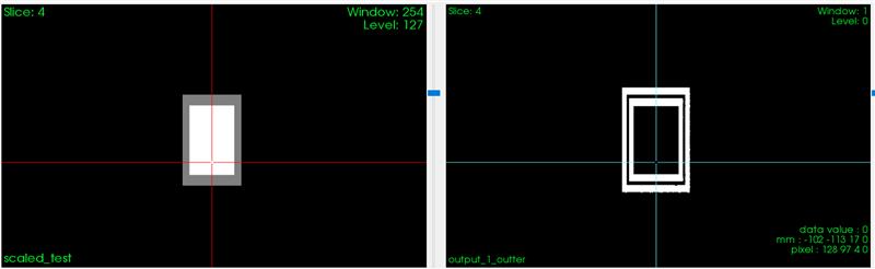
To edit this further, if i create a squared cone, taking a reference image from my dataset and saved an artificial image, and it seems to be working fine. Now I’m more confused than ever.
You can solve this quite easily by creating two separate segments - one for the outer surface of the myocardium, the other for the contrast agent inside. Once you have converted the planar contour representation to binary labelmap representation, subtracting the contrast agent segment from the myocardium a segment is trivial.
If the conversion tool you are working with still cannot handle this then you can do it with SlicerRT’s planar contour to closed surface converter. The easiest way to do it is probably by writing a simple Python script that constructs a vtkPolyData containing a list of planar polygons. You can then provide this as a segment to 3D Slicer, which can automatically convert to closed surface, binary labelmap, etc.
A full example that converts OsiriX ROI files (see examples) using this technique is available here. If you get stuck at any point then let me know. If you have an example then I can also see if I can quickly put together the code snippet you need.
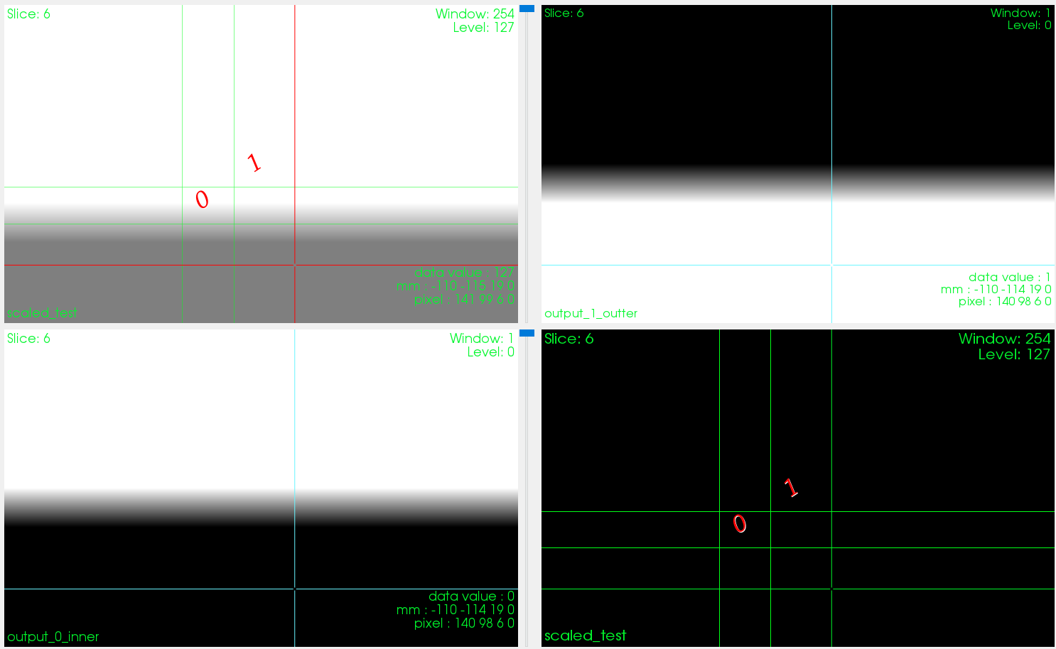
Thank you for your responses, I will have to look into slicer in general, visualization toolkits and in general toolkits in the medical image analysis are giving me quite the spooks but I better get started sooner than later! I think this won’t be necessary after all. I managed to locate the issue, the small segment that i wrote for the example above made me realize that I gave it the identity matrix as it’s affine matrix.
Then it got me thinking, what if swap out the affine matrix of the images with the identity matrix, pass them through the tool and then restore the original affine matrix? Well turns out that works. I’m unsure if this is something I did wrong in the code myself or the underlying works of clitk library are to blame, but for something i will probably use once with this dataset, I believe this bandaid fix will do however inefficient it might be!
Going to post a final update to my troubles as i figured out that the problem lies in the rounding of the affine matrix within my pipeline. I wrote this script (here) that generates a cubed cone and it’s contour file in various configurations. Pretty creepy that for our voxel size (0.23x0.23x1.5mm) the rounding error gives an discrepancy of about 3mm!