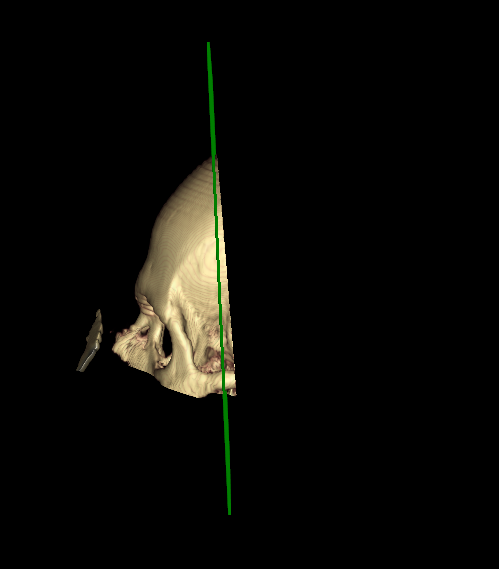
I have 3D volumetric data (ie. CT datasets), where I want to show a reconstruction plane using vtkImageReslice and cut the volume at that same position using the SetClippingPlanes function of the vtkVolumeMapper. This works well in general, but I run into problems with gantry tilted data (For the correction I use ITK and a shear matrix). The slice displayed by vtkImageReslice seems accurate, but the volume is cut at the wrong position:
If the gantry-tilt correction is done before the data is loaded into VTK, then it seems that the gantry tilt should be unrelated to the problem that you are seeing. Is the same vtkImageData used for both the input into vtkImageReslice, and the input into the vtkVolumeMapper?
Do you use any matrices in VTK itself, for example do you use SetUserMatrix() or SetUserTransform() with the vtkVolume? If so, what are the values in these matrices (specifically, are they orthogonal matrices?)
I might need to see the code to get an idea of where the problem is.
Hi David,
I agree with you that the gantry tilt should be unrelated. Furthermore, I also use ITK to reorient sagittal / coronal images to axial, and there are no such problems in these cases.
I also do not use any user transforms.
I’d probably have to isolate the problem in a sample project, and will share it if I encounter it there.
I just had time to analyze this problem further, and I assume it is because of the gantry tilt correction. The vtkImageReslice requires a normal vector, and the length vector I get for gantry tilted images is not 1, so I assume this might be the problem?
I have to check the way I convert from DICOM coordinate system to VTK, due to gantry tilt the norm of my column vectors is not 1.
Edit: I actually managed to solve it. The problem was that I calculated the cross product of the row and column vector of the desired plane, and then transforming from DICOM coordinates to VTK coordinates. I changed it from first transforming both vectors, and then computing the cross product for the normal. That worked for matrices with rotations / mirroring, but not the gantry tilt shear.
Hi Marius,
Thank you for your post. I have a few questions about the coordinates you mentioned here. For VTK coordinates, do you mean the coordinate after gantry tilt correction (done outside of VTK)? And what is the DICOM coordinate, are those vectors (0,0,1), (1,0,0) and (0,1,0)?
Does the result of the normal vector become different because of the shear? If only rotation exists, will the normal still be different from the two ways of transformation?
Thanks.
Hi Jiacheng,
what I do is the following. I load the DICOM data into vtk and set the spacings accordingly. I now want to e.g. draw a line at the given position using DICOM coordinates (e.g. directly taking the Patient Position of the first slice, so it is located on the upper left corner of the volume). I build an affine transform containing the Row, Column and Slice Orientation in the first three column vectors, and the Patient Position for the translation component.
Now to get from “DICOM coordinates” to my VTK coordinates, I apply the inverse of that matrix to the DICOM coordinate, which gives me the location in “VTK space”.
Additionally I want to correct the shear induced by the gantry tilt, so I additionally apply this shear matrix. So lets say my final matrix is called T = GT * PM, where GT is the gantry tilt correction matrix, and PM the patient matrix.
My problem was now that assuming if I take the cross product of vectors in “DICOM space” and then transforming, is the same as transforming the vectors first and then applying the transform, but
T(v_1) x T(v_2) != T(v_1 x v_2)
Hope this helps