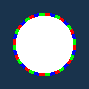
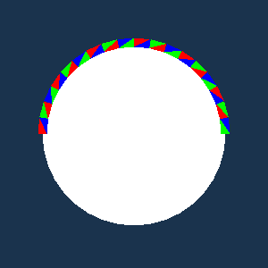
I am writing an application that renders edges using simple lines with coloring based on a scalar value and lookup table. On linux and my older intel-based mac the following simple example works as expected, with edge color cycling r-g-b-r-g-b etc around the perimeter of the circle. On mac m1, however, I observe the result that only half the edges get rendered, and each edge (which appears to consist of 2 triangles) gets two different colors in the r-g-b sequence.


here is the code:
#include <vtkSmartPointer.h>
#include <vtkPolyData.h>
#include <vtkPoints.h>
#include <vtkCellArray.h>
#include <vtkTriangle.h>
#include <vtkActor.h>
#include <vtkPolyDataMapper.h>
#include <vtkRenderWindow.h>
#include <vtkRenderer.h>
#include <vtkRenderWindowInteractor.h>
#include <vtkProperty.h>
#include <vtkLine.h>
#include <vtkMath.h>
#include <vtkFloatArray.h>
#include <vtkIntArray.h>
#include <vtkDoubleArray.h>
#include <vtkCellData.h>
#include <vtkLookupTable.h>

int main(int, char *[]) {

  // Create points for the circle's center and perimeter
    const double radius = 1.0;
    const int numSegments = 36;
    double center[3] = {0.0, 0.0, 0.0};

    vtkSmartPointer<vtkPoints> points = vtkSmartPointer<vtkPoints>::New();
    points->InsertNextPoint(center);

    // Create points around the circle
    for (int i = 0; i < numSegments; ++i) {
      double angle = 2.0 * vtkMath::Pi() * i / numSegments;
      double x = center[0] + radius * cos(angle);
      double y = center[1] + radius * sin(angle);
      points->InsertNextPoint(x, y, center[2]);
    }

    // Create triangles for the circle
    vtkSmartPointer<vtkCellArray> triangles = vtkSmartPointer<vtkCellArray>::New();
    for (int i = 1; i <= numSegments; ++i) {
      int next = (i % numSegments) + 1;
      vtkSmartPointer<vtkTriangle> triangle = vtkSmartPointer<vtkTriangle>::New();
      triangle->GetPointIds()->SetId(0, 0);  // Center point
      triangle->GetPointIds()->SetId(1, i);  // Current point on the circle
      triangle->GetPointIds()->SetId(2, next);  // Next point on the circle
      triangles->InsertNextCell(triangle);
    }

    // Create polydata for the circle
    vtkSmartPointer<vtkPolyData> polyData = vtkSmartPointer<vtkPolyData>::New();
    polyData->SetPoints(points);
    polyData->SetPolys(triangles);

    // Create a mapper and actor for the circle
    vtkSmartPointer<vtkPolyDataMapper> mapper = vtkSmartPointer<vtkPolyDataMapper>::New();
    mapper->SetInputData(polyData);

    vtkSmartPointer<vtkActor> actor = vtkSmartPointer<vtkActor>::New();
    actor->SetMapper(mapper);

    // ========================
    // edges...
    // ========================

    // Create the edge using lines
    vtkSmartPointer<vtkCellArray> lines = vtkSmartPointer<vtkCellArray>::New();

    // and add a scalar for coloring with a lookup table...
    //vtkSmartPointer<vtkFloatArray> scalars = vtkSmartPointer<vtkFloatArray>::New(); // all array types produce same issue
    vtkSmartPointer<vtkIntArray> scalars = vtkSmartPointer<vtkIntArray>::New();
    //vtkSmartPointer<vtkDoubleArray> scalars = vtkSmartPointer<vtkDoubleArray>::New();
    scalars->SetNumberOfComponents(1);
    scalars->SetName("EdgeScalars");

    for (int i = 1; i <= numSegments; ++i) {
      int next = (i % numSegments) + 1;
      vtkSmartPointer<vtkLine> line = vtkSmartPointer<vtkLine>::New();
      line->GetPointIds()->SetId(0, i);
      line->GetPointIds()->SetId(1, next);
      lines->InsertNextCell(line);

      // alternate scalar values 0,1,2,0,1,2...
      scalars->InsertNextValue(i%3);

    }

    // Create a polydata for the edge
    vtkSmartPointer<vtkPolyData> edgeData = vtkSmartPointer<vtkPolyData>::New();
    edgeData->SetPoints(points);
    edgeData->SetLines(lines);
    edgeData->GetCellData()->SetScalars(scalars);

    // r,g,b, lookup table...
    vtkSmartPointer<vtkLookupTable> lut = vtkSmartPointer<vtkLookupTable>::New();
    lut->SetNumberOfTableValues(3);
    lut->SetTableValue(0,1.0,0.0,0.0);
    lut->SetTableValue(1,0.0,1.0,0.0);
    lut->SetTableValue(2,0.0,0.0,1.0);

    // Create a mapper and actor for the edge
    vtkSmartPointer<vtkPolyDataMapper> edgeMapper = vtkSmartPointer<vtkPolyDataMapper>::New();
    edgeMapper->SetInputData(edgeData);

    edgeMapper->SetScalarRange(0,2);
    edgeMapper->SetLookupTable(lut);

    vtkSmartPointer<vtkActor> edgeActor = vtkSmartPointer<vtkActor>::New();
    edgeActor->SetMapper(edgeMapper);

    //edgeActor->GetProperty()->SetColor(1.0, 0.0, 0.0); // Red color for the edge (when not using lut)
    edgeActor->GetProperty()->SetLineWidth(10.0);       // Thickened edge

    // Create a renderer, render window, and interactor
    vtkSmartPointer<vtkRenderer> renderer = vtkSmartPointer<vtkRenderer>::New();
    vtkSmartPointer<vtkRenderWindow> renderWindow = vtkSmartPointer<vtkRenderWindow>::New();
    renderWindow->AddRenderer(renderer);
    vtkSmartPointer<vtkRenderWindowInteractor> renderWindowInteractor = vtkSmartPointer<vtkRenderWindowInteractor>::New();
    renderWindowInteractor->SetRenderWindow(renderWindow);

    // Add the actors to the scene
    renderer->AddActor(actor);
    renderer->AddActor(edgeActor);
    renderer->SetBackground(0.1, 0.2, 0.3); // Background color

    // Render...
    renderWindow->Render();

    // interact...
    renderWindowInteractor->Start();

    return EXIT_SUCCESS;
}
A couple other clues to this problem: if the edges do not add the scalar for coloring (i.e. no scalar, no lookup table, and we simply color the actor red), all platforms tested produce the correct result, with all edges rendered in red around the full circle.
You can see from the code above that I tried several different types for the edge-based scalar. None of these choices correct the problem (int, double, float).
The issue may be related to the following august post on edge rendering with mac:
Any help would be appreciated, as this issue is preventing us from developing edge highlighting and selection routines for m1,2,3 builds. Thanks!