Hi - here’s the case I’m trying to solve (well, optimize really). We have a Frustum and a polydata, and we want to do the following:
Only get the data within the frustum (which we can do with vtkClipPolyData and the frustum planes)
Remove cells with normals that aren’t facing the origin of the frustum (which we do with a vtkPolyDataNormals filter)
Remove any cells that are completely obscured by other cells from the origin’s point of view.
We are currently doing the last step by brute force (which takes way longer than I want), but I have to imagine there is some way to do this in VTK. Any pointers?
Are you using a locator? You can call IntersectWithLine for each point in the polydata (using the line from the origin to that point) to see if there are intersections before that point. With a locator, this should be fast. A cell with no visible points can be culled, which is I guess what you’re doing already.
If you want real efficiency and are willing to go beyond VTK’s built-in capabilities, you can apply a projective transformation to the polydata. Then all the lines for intersection tests would be purely in the Z direction, and a line intersection algorithm could be coded to be very fast. Note that this transformation can also speed up the frustum check, since the projective transformation turns the frustum into a simple bounding box. Also, for the normals, you’d only have to check the sign of the z-component of the normals.
Yes, we’re using a locator. Right now we’re just for-looping through all the points, but for a model with 750k points it is still taking a while (40 seconds or so to run through this step). Looking into vtkStaticCellLocator to see if I can thread this work out instead of having it run serially in the for loop.
I’m curious about your second point - what do you mean by a projective transformation?
I looked at vtkFrustumCoverageCuller, but a) it seems to be something that the rendering system uses directly (?) and b) I couldn’t figure out a way to use it (no examples for it sadly).
By a projective transformation, I mean the same kind of transformation that a camera uses. The vtkPerspectiveTransform can be used to create one in the same manner that the camera does (using the vtkPerspectiveTransform::SetupCamera() and vtkPerspectiveTransform::Perspective() methods). Once created, it can be applied to the data with vtkTransformPolyData. So this gives you two copies of your data, one in the original data coordinates, and another that has been transformed to view coordinates (i.e. viewed from a camera’s perspective). Then you can do the cell culling in view coordinates, where the math should be simpler.
Edit: actually the transform’s SetupCamera() and Frustum() methods would probably work better in your case than SetupCamera() and Perspective().
If you apply the projection matrix (a.k.a. projection transform) to your geometry, you’ll have it in homogeneous coordinates such that now it is relatively easy to do occlusion tests. I believe vtkCamera::GetProjectionTransformMatrix() (VTK: vtkCamera Class Reference) returns the matrix you can use for this.
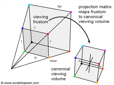
OK I’m starting to wrap my head around this. When I use the transformation matrix to put the poly data in the canonical viewing volume,
Anything outside the volume wouldn’t get rendered (this duplicates the poly data clip via the frustum)
Some points for a triangle could be inside the volume, some out; so I could cull based on whatever criteria I want
The thing I’m missing is how z-depth gets handled. If I have a set of triangles blocking another triangle deeper in the view, does it just not get put into the volume like 1) above, since the camera wouldn’t display it? If so, that’s great because that is where my bottleneck is.
The projection transform is still just a transform, it doesn’t do any culling on its own. It just makes the culling easier.
If you correctly apply vtkPerspectiveTransform to the data, then your frustum bounds will map to a nice little cube with bounds of [-1, +1, -1, +1, -1, +1] in what we call view coordinates (or maybe it’s called viewport coordinates, sometimes I confuse the names).
So culling based on bounds becomes trivial since any point with x, y, or z outside of the range [-1, +1] is out of view. Any cell with all points out of view can be culled. In these coordinates, the depth maps from -1 to +1 (unlike e.g. display coordinates where depth goes from 0 to 1).
For occlusion, the camera relies on the depth buffer on the GPU, i.e. the occlusion isn’t handled until the data is actually rendered. But you want to deal with the occlusion before then, right? So you still have to handle the occlusion yourself. My point, though, is that it might be easier to deal with in view coordinates than in the original data coordinates. You can probably work things out from there.
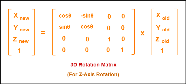
The figure below illustrates how one uses a transform matrix to calculate the result:
The left hand term is the new XYZ of one point of your geometry. The 4x4 matrix is your transform matrix which, in this case, is a rotation about the Z axis. The right hand term is the original XYZ location of one point of your geometry. The 4th row/column in the matrices for 3D transforms are needed to allow projective geometry computations such as the one you need.
Now, replace the rotation matrix above with VTK’s projection matrix and perform this calculation for every vertex of your geometry that lie inside the frustum. If you want to delve into the wonderful world of Computer Graphics/Geometry, I recommend reading a primer such as Graphics Gems (Amazon.com).