Hello.
I try to prepare data for cnn (convolutional neural network) - metastatis brain cancer MRI. I have for each patient series of dicom files (slices) and vtk file (points and polygons). In the viewer I see file with vtk extention as 3d picture. I need to split 3d vtk picture into series of masks and find appropriate dicom file for each mask. Could you please help me and clarify how I can process file with vtk extention and gey series of 2d slices from it and find appropriate dicom slice using python or VTK?
Usually the output you want pairs of grayscale 3D volume (MRI) and matching 3D binary labelmap (ground-truth segmentation). You can slice a 3D image loaded as a numpy array using simple indexing, but usually preprocessing is more involved than that (you may want slice, scale, crop, normalize, augment, etc).
It may worth reconsidering using 2D kernel as that way you would not be able to utilize context from adjacent slices. Brain MRIs are small and tumor shapes are usually simple enough so the computational cost should be bearable. You can try NVidia Clara Train (if you create a model then you can already use it in Segment Editor), NiftyNet, etc.
You may also consider starting from pre-trained models for tumor segmentation on MRI that you can evaluate/improve with your own data - see NiftyNet model zoo and Nvidia Clara models). You can try existing NVidia Clara brain tumor segmentation model in 3D Slicer, in a few minutes, without any programming, as shown in this video.
Andras, thank you very much. One more question. I agree that 3d Cnn is better then 2d for this case. I can convert dicom slices (or .nrrd file) to 3d numpy array. But I don’t know how convert .vtk file to 3D numpy array. POINTS is really 3d numpy array, but how convert polygons? Are there any functions in 3D slicer or any python library for it?
A .vtk file can contain image data, polydata, unstructured grid, etc. What do you have in yours?
My /vtk file has following structuire:
vtk DataFile Version 4.2
vtk output
ASCII
DATASET POLYDATA
POINTS 109382 float
-37.2217 -29.809 -9.85098 -37.0058 -30.0193 -9.81293 -37.1069 -30.4734 -12.9625
…
-21.5091 5.62117 56.814 -21.0796 5.62067 56.8002
POLYGONS 218728 874912
3 0 1 2
3 3 2 1
…
3 109380 108436 109381
3 109381 108436 108404
POINT_DATA 109382
NORMALS Normals float
0.703098 0.692624 -0.161015 0.702831 0.690654 -0.17037 0.703527 0.699859 -0.123484
…
-0.0314577 -0.209089 -0.97739 -0.0314568 -0.209091 -0.97739
As I understand Polygons creates a contour along the borders of the tumor (using POINTS above or normalized POINTS from last part of file). I need 3d numpy array that was filled by 1 inside this countour and by 0 outside it.
You seem to have a triangle mesh (polygons consisting of 3 points) and not parallel contours. They can be converted to binary labelmaps using very different methods.
What software generated these VTK files?
Could you please load the file into 3D Slicer or Paraview and show a screenshot to confirm what exactly do you have in the polydata?
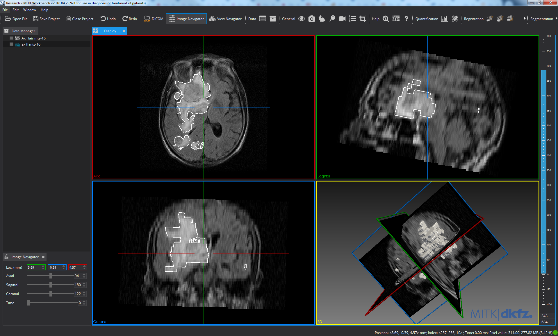
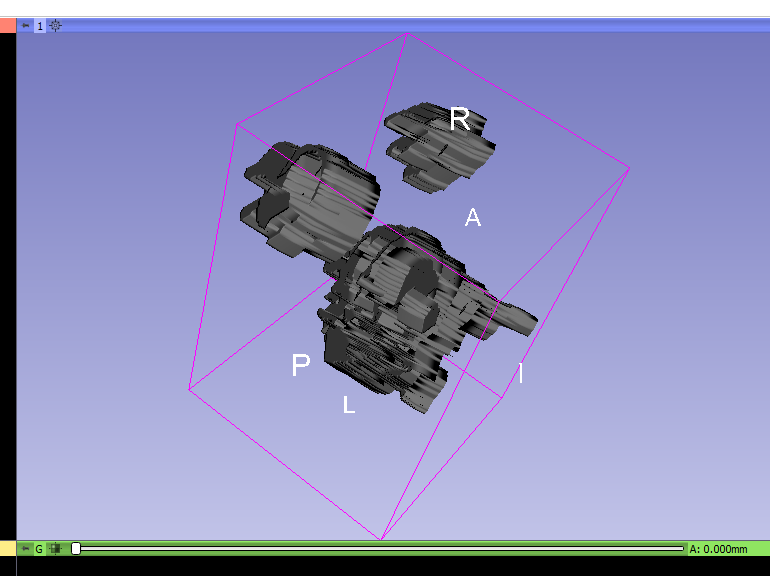
OK. This is a closed surface mesh, which should be no problem to convert to binary labelmap. You can do it using VTK, using vtkPolyDataToImageStencil class as shown here.
If you find it hard to figure out the necessary coordinate system transforms then you can use the converter in 3D Slicer. Using the GUI: load the image data and model (vtk) files, create segmentation for the image (right-click on image -> Segment this), import the model into the segmentation (drag-and-drop the model to the segmentation node), then export the segmentation to binary labelmap (right-click on segmentation -> Export to binary labelmap):
You can save the binary labelmap as a nrrd or nifti file or access it directly as a numpy array. You can automate all the above steps using a few lines of Python script (see examples here). If you have any questions related to 3D Slicer, post it to Slicer forum.
If you do the segmentation in MITK Workbench then probably you can directly save it as a nrrd or nifti file (that you can load as a numpy array, without any conversion).
I’ve also noticed that the segmentation is very low quality, due to the highly anisotropic input image (image spacing is about 5-10x larger along one of the axis). You may want to resample your input volume to be isotropic before segmenting it (you can do this in 3D Slicer using Crop volume module, by enabling “Isotropic spacing” option) to be able to create smoother, more detailed segmentation.
Thank you very much for the detailed explanation. I am a student and this is my first project. You helped me a lot. (Sorry to answer late. I was sick all the holidays - the flu)
Hi!
Perhaps my question is out of scope this forum. Exuse me.
Could you please advice some python library with pipeline for preprocessing brain MRI before CNN processing for tumpr segmentation. I would use it in Google Colab if it is possible. Thank you in advance.
Yes, it is hard to transform coordinate system using vtkPolyDataToImageStencil .The python scripts 25 is missing, could you share it again? Thank you!
Does the VTK file contain an image or a mesh?
What coordinate system does the file use (RAS or LPS)?
Script repository is moved to a new location.
The VTK file contains a poly mesh of ground truth. I am not sure which system is used. The vtk is provided by others. Can the system be neither RAS or LPS?
If the coordinate system is neither RAS nor LPS then go back to the people who created the data set and ask them to save in LPS. Most likely they used a library to read the DICOM image that did not reconstruct the image correctly in phsyical space, or they did not use the data correctly, or they ignored the physical space and instead created the mesh in IJK voxel coordinate system.
Thank you so much! The guy extracting mesh files will reply this Friday.
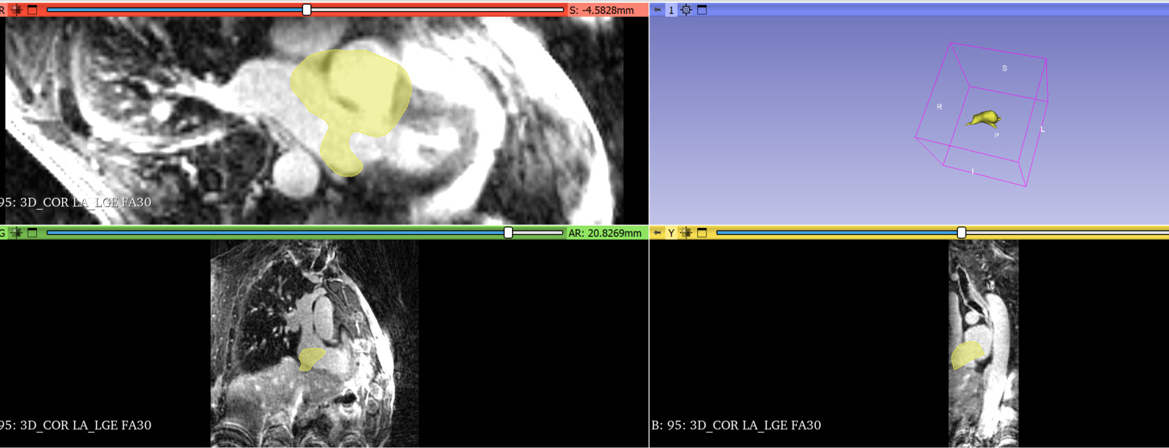
I have another question. Look at Figure 1. Dicom images have an obvious rotation around the LR axis. I guess the Dicom image system is not LPS. Am I right? This dicom’s patient orientation is [-0.71, 0.71,0,0,0,-1]. That might be the reason why the ground truth (yellow part in Figure 1) is not aligned?
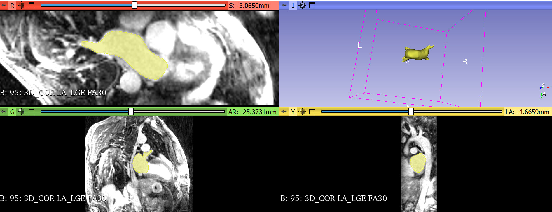
I rotate the mesh around the LR axis in Slicer; the rotated mesh model can be aligned with dicom images in Slicer, as shown in Figure 2.
Figure 1:
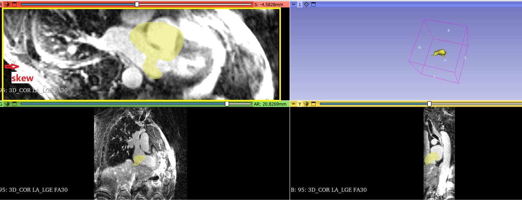
Figure 2:rotate the mesh model around the LR axis
DICOM images are always In LPS (unless the imaging technician makes a mistake when the image is acquired). If the image orientation appears incorrect in Slicer then most likely the software that the group used did not reconstruct the 3D image correctly. They could use Slicer to read the DICOM image into a 3D volume and save it in NRRD format to avoid this problem.