How to combine vtkImageData?

Hello everyone,

I'm wondering if someone could help with an issue I'm trying to address. I have a situation where I would like to combine at least 2 vtkImageDatas (A & B) that could possibly have the following characteristics

  • different dimensions
  • different scalar types

My initial approach after doing some digging was to either

  1. write a function to determine the overall dimension that encapsulates both vtkImageDatas (A & B) (taking into consideration attributes such as spacing) and then generate a new vtkImageData with the new dimension, spacing and subsequently fill the data.
  2. use vtkImageAppend and add both image data (A & B) to generate a combined vtkImageData

I quickly realised couple of issues with
#1 - here this approach seems to expect that the final vtkImageData must be of a specific scalar type & spacing (are these of Data A or Data B)? Also what scalar values are to be filled into the resulting vtkImageData (would that be from A or B).

#2 - Using vtkImageAppend seems to be the safest approach however it requires that the datas to combined must be of the same scalar types.

Does anyone have any idea if what I’m trying to achieve is even possible?

Hi Seun,

I use vtkImageReslice for this, since it can do the padding, cropping, resampling, geometric transformations, and scalar type conversion all at the same time.

For changing the scalar type, it has SetOutputScalarType(), SetScalarShift(), and SetScalarScale() (the Shift/Scale are for rescaling the values).

The padding/cropping are controlled via SetOutputExtent(). Alternatively, the SetInformationInput() method can be used to set the output extent/spacing/etc to be the same as an existing data set.

Another option for setting the extent is to add an observer for the ExecuteInformationEvent, and then your observer can change the extent as part of the pipeline execution.

Hello David,

Thanks for the reply. I have couple of questions, just to be a bit more clear I’m using the reslicer as part of my pipeline. Basically I have a set up as follows

image_data_A and image_data_B 
(as information-input & input-data respectively) --> Reslicer

(said)Reslicer & Lookup table --> vtkimageMapToColor

vtkimageMapToColor --> vtkImageBlend

That's pretty much my setup, my issue in understanding the Reslicer is what led me to my initial post as I was under the impression that the reslicer couldn't magically compose both images A & B (despite their differences in scalar types, spacing & dimension) and that I need to either do the work myself or rely on another VTK algorithm (in this case you say the vtkImageReslice can perform these tasks).

With regards to For changing the scalar type, it has SetOutputScalarType() , SetScalarShift() , and SetScalarScale() (the Shift/Scale are for rescaling the values).

Pardon me but I’m still unclear about the usage, wouldn’t 'SetOutputScalarType()` for instance require I decide on the particular scalar type the result ought to be as opposed to the Reslicer deciding the best type that fits the current task (ie: if I provide image A with floats as scalar types and image B as int type) do I need to set the Reslicer’s output scalar type to one of them or can it decide ?

I believe the same uncertainty described above with respect to setting the output scalar type applies to scalar shift and scalar scale.

Thanks

You’re absolutely correct on that point. None of the decisions would be made by vtkImageReslice. It has to be told exactly what to do. That’s where observers can be handy, since the logic for the decisions can be put in an observer.

For reslicing before blending, if the blending is going to be done using RGB, the vtkImageResliceToColors filter can be used to perform mapping from grayscale to RGB. If the blending is going to be done as some other pixel type (e.g. 16-bit grayscale or floats), then vtkImageReslice with a shift/scale applied to the values to make them comparable before the blend.

Hello David,

It makes sense that it's up to the programmer (me) to me decide on how to configure the final output of the reslicer. I'll also take a look at the suggested 'vtkImageResliceToColors' it may have something useful for me. I'll test things out at my end and reach out if I encounter any more issues. Thanks a lot

Hello David,

I’m currently trying to implement your suggestion however I’m stuck with an issue. Say for example I have the following images

  • image_A (2 x 10 x 1) → float (assume this image is used as the information input)
  • image_B (9 x 8 x 1) → int

and I’d like to generate a resliced image that encompasses both so final image ought to be 9x10x1.

If I take the approach of using ‘SetOutputExtent’ I believe I’ll have to specify an extent of 9x10x1 and decide what scalar type to use for the final result (I can go with int or float in the case of the example above). What I’m not clear about using this approach is it seems to me I’ll have to figure a way to copy the image-data A used as my information input into a new image data of 9x10x1 in the exact region because I noticed when I set image_A as my information input → the result from the reslicer is not of size 9x10x1 but that of image_A (2 x10x1) which isn’t what I’m trying to achieve. If indeed I need to copy image_A into the exact region in the resulting image with dimension (9x10x1) do you have any idea or links of examples on how to do so?

Currently, I’m setting the output scalar to my choice, I’m determining the overall extent that accommodates both images but it seems there’s something missing.

Thanks

It’s fine to use both SetInformationInput and SetOutputExtent, the values for SetOutputExtent() are the ones that will be used. So it shouldn’t be necessary to build your own image to use as the InformationInput. But you will need code to compute the combined extent.

Do these images already have the same pixel spacing/origin? If not, then you will actually have to compute a bounding box that contains both images (using the Bounds of the image), decide on a spacing and origin for the output, and then compute the Extent that corresponds to the bounding box.

Thanks David, I’m already doing this because my images tend not to have the same spacing at times so I have to make sure the bounds calculation is correct.

I’ll continue at it maybe I’m missing something. Thanks a bunch

Hello David,
do you mind pointing me in the right direction with respect to how one determines the scalar scale & scalar shift? In my previously posted example with the 2 images of different scalar types & dimension. what determines the shift & scale. I had a look at the API and couldn’t quite wrap my head around how to deploy these two functions.

The ScalarShift and ScalarScale allow you to map from one scalar range to another scalar range.

The trivial example is scaling an MRI from its original range e.g. [0,2532] to a new range of [0,255]. In this case, one would use ScalarShift=0 and ScalarScale=(255.0/2532.0).

The general equation for mapping the range [A,B] to a new range [X,Y] is the following, where a is the input and x is the output:

x = X + (a - A)*(Y - X)/(B - A)

The way to achieve this mapping with ScalarShift and ScalarScale is

SetScalarShift( X*(B - A)/(Y - X) - A )
SetScalarScale( (Y - X)/(B - A) )

If the desired output scalar range starts at zero (which is usually the case), this simplifies:

SetScalarShift( -A )
SetScalarScale( Y/(B - A) )

Thanks a lot David for the detailed response, I’ll try to implement it and get back to you, hopefully I can get it right. Huge thanks.

Please note that I had a typo in my last message:

where a is the input and b is the output
where a is the input and x is the output

Hello David,

I’ve been trying to implement all what we discussed above thus far and still finding it a bit difficult. please bear with me, this is what I’m trying to achieve.

There are 2 image datas I’m using
Lets call them A & B

A is as follows (ScalarType - VTK_FLOAT) spacing 1x1x1

and
B is as follows (ScalarType - VTK_SHORT) spacing 1x1x1
Screen Shot 2022-07-15 at 10.58.48 AM

Bearing in mind the overall pipeline discussed earlier

image_data_A and image_data_B
(as information-input & input-data respectively) → Reslicer

(said)Reslicer & Lookup table → vtkimageMapToColor

vtkimageMapToColor → vtkImageBlend

Below is a snippet of the code I’m working with in particular relating to the reslicer.


// Note, this algorithm runs twice for the setup, once for image A and for B. The first time around image = reference image = image A, so we basically setting up the first image. The 2nd time around image is the image = image_B but not the reference image (A). We keep a handle for the reference image (A) once it's set the first time.
 
                if (image)
				{
					slicer = vtkSmartPointer<vtkImageReslice>::New();
					slicer->SetInputData(image);
					
					
                    // implementation of extent / scale / shift
                    //========================================
					int composedDimension[3];
					double composedSpacing[3];
					estimateBounds(referenceImageData, image, &composedDimension[0], &composedSpacing[0]);
					
					slicer->SetOutputExtent(0, composedDimension[0], 0, composedDimension[1], 0, composedDimension[2]);
					slicer->SetOutputScalarType(referenceImageData->GetScalarType());
					slicer->SetOutputSpacing(composedSpacing[0], composedSpacing[1], composedSpacing[2]);
					
					/*
						 a -> input
						 x -> output
						 
						 x = X + (a - A)*(Y - X)/(B - A)
						 The way to achieve this mapping with ScalarShift and ScalarScale is

						 SetScalarShift( X*(B - A)/(Y - X) - A )
						 SetScalarScale( (Y - X)/(B - A) )
						 If the desired output scalar range starts at zero (which is usually the case), this simplifies:

						 SetScalarShift( -A )
						 SetScalarScale( Y/(B - A) )
					 */
					
					double rangeIn[2];
					image->GetScalarRange(&rangeIn[0]);
					
					double rangeOut[2];
					image->GetScalarRange(&rangeOut[0]);
					
					double scalarShift = (rangeOut[0] * (rangeIn[1] - rangeIn[0]) / (rangeOut[1] - rangeOut[0]) - rangeIn[0]);
					double scalarScale = (rangeOut[1] - rangeOut[0]) / (rangeIn[1] - rangeIn[0]);
					
					slicer->SetScalarShift(scalarShift);
					slicer->SetScalarScale(scalarScale);
					//========================================

					slicer->SetInformationInput(referenceImageData);
					slicer->SetOutputDimensionality(3);
					slicer->SetBackgroundLevel([theGrid minVoxelValue]);

                            vtkSmartPointer<vtkTransform> finalTransform = vtkSmartPointer<vtkTransform>::New();
				finalTransform->Identity();
			slicer->SetResliceTransform(finalTransform);

// SLICER is then sent to ImageMapTOColor.

Now the issue I’m seeing is that using the above code setup

  1. If my referenceImageData which I tend to set as the Information Input starts off as Image-A and the inputData is image-B with the much larger dimension. here is what I perceive

before deploying the Code

and after deploying the code

  1. If I reverse the situation this time using image-B as the Information Input and as my reference data and image-A the smaller image data (with scalar float) as my input data. Here is what I’m seeing

before deploying code

and after deploying the code

I'm getting completely different behaviour in both scenarios. One thing I must mention is you may have noticed I'm using a separate function (estimateBounds) I wrote to estimate the overall bounds required and I'm using the larger detected spacing on comparing both image-datas to estimate the output spacing for my result. See function below

static void estimateBounds(vtkSmartPointer<vtkImageData>& imageA,
						   vtkSmartPointer<vtkImageData>& imageB,
						   int* ioDimension,
						   double* ioSpacing)
{
	// Bounds are typically (min x , max x, min y, max y, ....) so we set the values opposing each bound limit.
	double bounds[6] = {
		VTK_DOUBLE_MAX, VTK_DOUBLE_MIN,
		VTK_DOUBLE_MAX, VTK_DOUBLE_MIN,
		VTK_DOUBLE_MAX, VTK_DOUBLE_MIN
	};
	
	// We are processing bounds of 2 images
	for (int idx = 0; idx < 2; idx++)
	{
		double origin[3];
		(idx == 0) ? imageA->GetOrigin(origin): imageB->GetOrigin(origin);
		
		int dimension[3];
		(idx == 0) ? imageA->GetDimensions(dimension): imageB->GetDimensions(dimension);
		
		// determine the min & max bounds
		for (int x = 0; x < 3; x++)
		{
			int index = x * 2;
			if (origin[x] < bounds[index])
			{
				// clamp bound min to origin.
				bounds[index] = origin[x];
			}
		}
		
		double spacing[3];
		(idx == 0) ? imageA->GetSpacing(spacing): imageB->GetSpacing(spacing);
		
		// determine the max bounds
		for (int x = 0; x < 3; x++)
		{
			double spacingValue = spacing[x];
			double maxBoundValue = origin[x] + dimension[x] + spacingValue;
			
			int index = (2 * x) + 1;
			if (maxBoundValue > bounds[index])
			{
				// clamp bound max to bounds value.
				bounds[index] = maxBoundValue;
			}
		}
	}
	
	// Note, this algorithm assumes image A will be the reference.
	double referenceSpacing[3];
	imageA->GetSpacing(referenceSpacing);
	
	double spacingB[3];
	imageB->GetSpacing(spacingB);
	
	for (int x = 0; x < 3; x++)
	{
		ioDimension[x] = static_cast<int>(ceil( (bounds[(x * 2) + 1] - bounds[x * 2]) / referenceSpacing[x] ));
		
		ioSpacing[x] = (referenceSpacing[x] > spacingB[x]) ? referenceSpacing[x] : spacingB[x];
	}
}

Could you kindly take a look at this?
It seems there’s something I’m not getting right. Thanks

Your estimateBounds() function doesn’t provide anything to be used as the Origin of the output image. It’s crucial to call SetOutputOrigin() on vtkImageReslice if you call SetOutputSpacing() and SetOutputExtent().

There is also a typo in the code here, where + spacingValue should be * spacingValue:

    double maxBoundValue = origin[x] + dimension[x] + spacingValue;

And there are off-by-one errors when going from dimensions to extent and back. If an image has 256 columns, then the column indices range from 0 to 255, so that’s what should be used as the extent.

Actually when overlaying a small image on a large image with vtkImageBlend, it can be useful to set the resliced extent of the smaller image to just a small sub-extent of the common extent. This allows vtkImageReslice to only produce the portion of the common extent that will actually be shown. On the downside, it means more math.

I’m thinking of putting together an example using some of VTK’s test data.

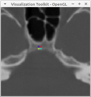
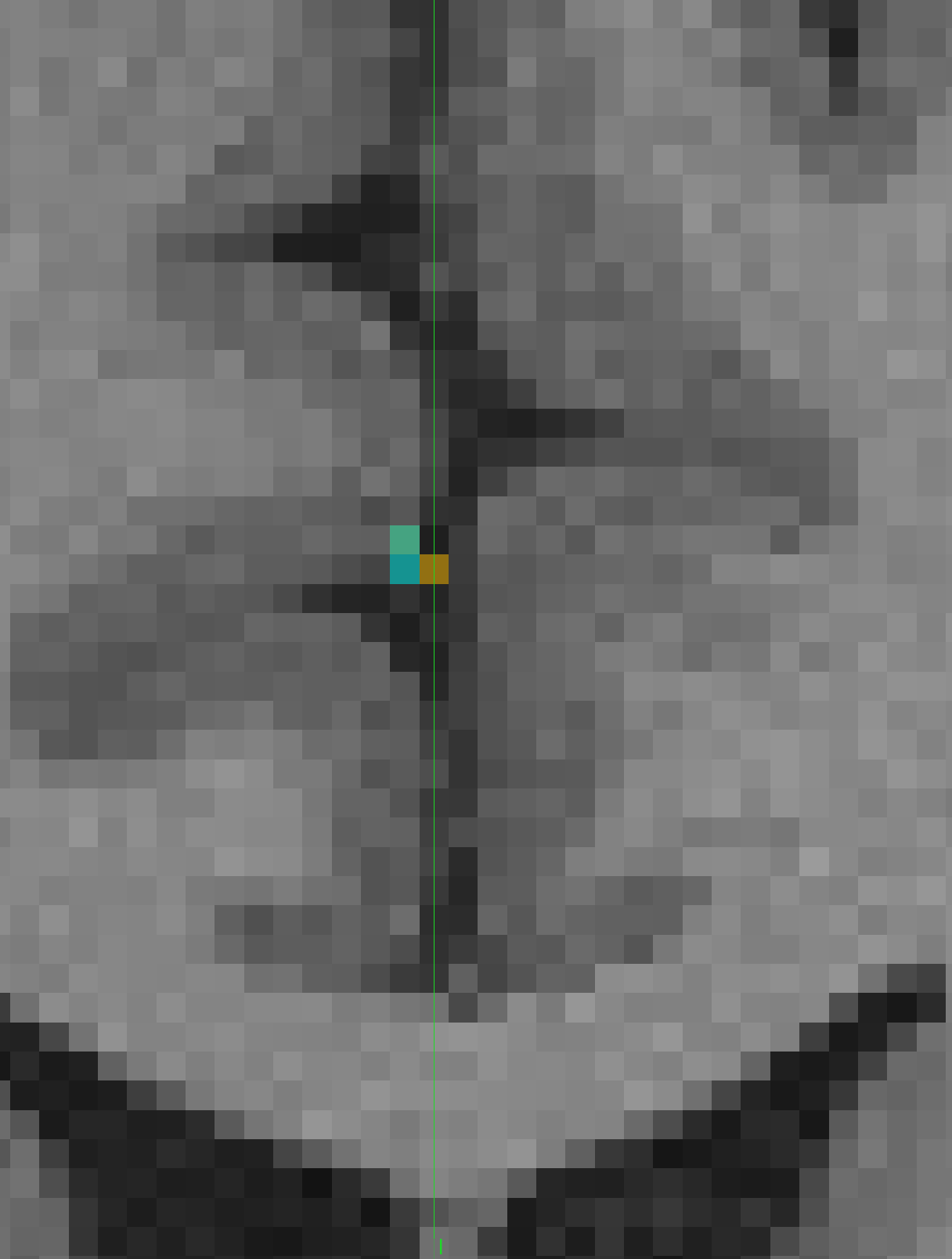
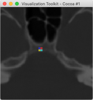
Here is an example of overlaying two images that are already in the same physical space but don’t have the same bounds or the same sampling. In this example, we set the OutputExtent of the overlay image to a cropped extent to avoid having vtkImageReslice produce a whole bunch of zeros for its background.

If the images are not in the same physical space, but there is a known transformation to go from the space of image A to the space of image B, then the math is different but the concepts are much the same.

You’ll have to excuse me for writing the example in Python.

"""
A simple example of overlaying two images.
The images must be in the same physical space, but can have different
position, size, and voxel spacing.
In this example, the Orientation of the images must be the identity matrix.
"""

import vtkmodules.all as vtk
import math

# for this example, any 256x256 image will do
brainfile = "ExternalData/Testing/Data/fullhead15.png"

def commonInformation(imageA, imageB):
    """Compute a new image geometry that encompasses two images.
    The first image will be used for the voxel spacing.
    Warning: if the two images are far apart, the resulting dimensions
    might be very large.
    """
    # compute common bounds
    bounds = [0.0]*6
    imageA.GetBounds(bounds)
    boundsB = imageB.GetBounds()
    for i in range(3):
        bounds[2*i] = min(bounds[2*i], boundsB[2*i])
        bounds[2*i + 1] = max(bounds[2*i + 1], boundsB[2*i + 1])

    # always use spacing from the primary image
    spacing = list(imageA.GetSpacing())

    # compute the new origin and dimensions: ensure that the new voxels are
    # sited at the same points as the primary image so that the primary image
    # will not have to be interpolated
    dimensions = [1]*3
    origin = list(imageA.GetOrigin())
    for i in range(3):
        lb = bounds[2*i]
        ub = bounds[2*i + 1]
        # compute the number of voxels by which the origin will shift
        offset = round((lb - origin[i])/spacing[i])
        origin[i] += spacing[i]*offset
        # use upper bound to get the dimension along this axis
        dimensions[i] = round((ub - origin[i])/spacing[i]) + 1

    return origin, spacing, dimensions

def setOutputInformation(reslice, origin, spacing, dimensions):
    """Given a vtkImageReslice filter, set the Output information.
    """
    reslice.SetOutputOrigin(origin)
    reslice.SetOutputSpacing(spacing)
    reslice.SetOutputExtent(0, dimensions[0] - 1,
                            0, dimensions[1] - 1,
                            0, dimensions[2] - 1)

def setOutputInformationWithCropping(reslice, origin, spacing, dimensions):
    """Given a vtkImageReslice filter, set the Output information.
    The output is cropped to the input bounds to increase efficiency.
    When blending, this can be applied to the overlay image, but not to
    the base image.
    """
    # the input data must be updated before this!
    inputImage = reslice.GetInput()
    bounds = inputImage.GetBounds()
    extent = [0]*6
    extentF = [0.0]*6
    for i in range(3):
        # crop to bounds
        extent[2*i] = int(round((bounds[2*i] - origin[i])/spacing[i]))
        extent[2*i + 1] = int(round((bounds[2*i + 1] - origin[i])/spacing[i]))
        # add a border to avoid boundary issues
        extent[2*i] -= 1
        extent[2*i + 1] += 1
        # clamp to dimensions
        extent[2*i] = max(extent[2*i], 0)
        extent[2*i + 1] = min(extent[2*i + 1], dimensions[i] - 1)

    reslice.SetOutputOrigin(origin)
    reslice.SetOutputSpacing(spacing)
    reslice.SetOutputExtent(extent)

# the first image is a brain
reader = vtk.vtkPNGReader()
reader.SetFileName(brainfile)
reader.SetDataOrigin(0.0, 0.0, 0.0)
reader.SetDataSpacing(1.0, 1.0, 1.0)
reader.Update()

# use the full scalar range of first image
imageA = reader.GetOutput()
rangeA = imageA.GetScalarRange()
tableA = vtk.vtkScalarsToColors()
tableA.SetRange(rangeA)

# the second image is a small activation area
imageB = vtk.vtkImageData()
imageB.SetDimensions(2, 2, 1)
imageB.SetOrigin(120.25, 130.25, 0.0)
imageB.SetSpacing(2.0, 2.0, 2.0)
imageB.AllocateScalars(vtk.VTK_UNSIGNED_CHAR, 1)
imageB.SetScalarComponentFromDouble(0, 0, 0, 0, 63)
imageB.SetScalarComponentFromDouble(0, 1, 0, 0, 127)
imageB.SetScalarComponentFromDouble(1, 0, 0, 0, 191)
imageB.SetScalarComponentFromDouble(0, 1, 0, 0, 255)

# use a color LUT for second image
tableB = vtk.vtkLookupTable()
tableB.Build()
tableB.SetRange(0, 255)

# compute the common grid for resampling the images
origin, spacing, dimensions = commonInformation(imageA, imageB)

# reslice first image to common space
resliceA = vtk.vtkImageResliceToColors()
resliceA.SetOutputFormatToRGB()
resliceA.SetLookupTable(tableA)
resliceA.SetInputData(imageA)
setOutputInformation(resliceA, origin, spacing, dimensions)
resliceA.Update()

# reslice second image to common space
resliceB = vtk.vtkImageResliceToColors()
resliceB.SetOutputFormatToRGBA() # RGBA for background transparency!
resliceB.SetLookupTable(tableB)
resliceB.SetInputData(imageB)
setOutputInformationWithCropping(resliceB, origin, spacing, dimensions)
resliceB.Update()

# blend and display the images
blend = vtk.vtkImageBlend()
blend.SetInputData(resliceA.GetOutput())
blend.AddInputData(resliceB.GetOutput())
blend.SetOpacity(1, 0.5)
blend.Update()

iren = vtk.vtkRenderWindowInteractor()
style = vtk.vtkInteractorStyleImage()
# use this for 3D images
#style.SetInteractionModeToImageSlicing()
iren.SetInteractorStyle(style)

win = vtk.vtkRenderWindow()
win.SetInteractor(iren)

ren = vtk.vtkRenderer()
win.AddRenderer(ren)

mapper = vtk.vtkImageSliceMapper()
mapper.SetInputData(blend.GetOutput())
blendExtent = blend.GetOutput().GetExtent()
mapper.SetSliceNumber(int((blendExtent[4] + blendExtent[5])/2.0))

actor = vtk.vtkImageSlice()
actor.SetMapper(mapper)
actor.GetProperty().SetInterpolationTypeToNearest()

ren.AddViewProp(actor)

win.Render()
ren.GetActiveCamera().Zoom(4.0)

iren.Start()

Output image:

overlay

Hello David,

Thanks a million for taking your time to help out, it's highly appreciated. It's obvious now that my estimateBounds function was naively written. I'll take a look at rewriting the function using your examples.

That’s okay, python is fine by me. I also see from your attached image it’s producing what I believe I expect.
Huge thanks David. I’ll try things out & get back to you. Pardon the late response by the way.

Hello David,

I have spent some time looking into this problem and trying to adapt your suggestion to my application.
I seem to be having some problem that I believe I don’t fully understand. If you don’t mind I’m wondering what would be the case if in the above code sample you provided, image A (the underlining image) is smaller than that of image B.

Basically if image A was of SetDimensions(2, 2, 1) and vice-versa for image B (the content of A).
Would the result be the same as that in the image you provided. I seem to be getting a completely different result at my end. If so, is there anyway to get both cases behaving the same way?
Thanks.

I tested this on the code above by applying the following change:

 # reslice first image to common space
 resliceA = vtk.vtkImageResliceToColors()
 resliceA.SetOutputFormatToRGB()
-resliceA.SetLookupTable(tableA)
-resliceA.SetInputData(imageA)
+resliceA.SetLookupTable(tableB)
+resliceA.SetInputData(imageB)
 setOutputInformation(resliceA, origin, spacing, dimensions)
 resliceA.Update()
 
 # reslice second image to common space
 resliceB = vtk.vtkImageResliceToColors()
 resliceB.SetOutputFormatToRGBA() # RGBA for background transparency!
-resliceB.SetLookupTable(tableB)
-resliceB.SetInputData(imageB)
+resliceB.SetLookupTable(tableA)
+resliceB.SetInputData(imageA)
 setOutputInformationWithCropping(resliceB, origin, spacing, dimensions)
 resliceB.Update()

The result was this image:
overlay

It’s a different result because alpha blending is not a commutative operation. Alpha blending is meant to model the effect of placing multiple semi-transparent films on top of one another, which itself is order-dependent.

You can try vtkImageBlend::SetBlendModeToCompound() to see if that blending mode suits your needs better. I’m not sure if it’s commutative, it was written by someone else for a specific purpose so YMMV.

Other blend modes could potentially be added to vtkImageBlend.

Hello David,

Pardon the late reply (it’s been a long weekend) and thanks a lot for the detailed response, from what you posted it seems there’s something wrong with how my application is setup. The difference in results you got is actually fine with me (I’ll also try the BlendModeToCompound) you mentioned to see if it works for me. I’ll try again to see if I can get to the bottom of things here. Thanks a lot for the help and most of all for being patient in answering.