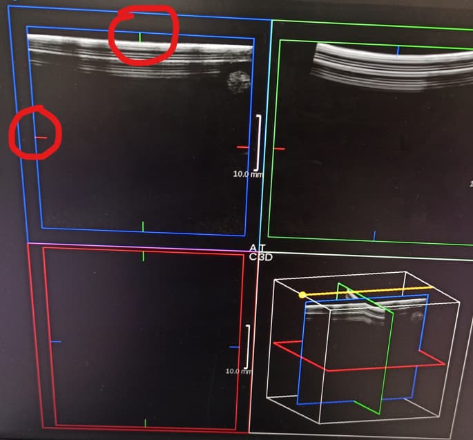
使用ipw的slice_position可以得到位置信息,根据当前ipw的平面的方向可以得到xyz的三个坐标值,这样就可以完整的得到一个线段的两个顶点。
代码如下:
#--coding:utf-8
#!/usr/local/bin/pvtkpython
import os
import sys
import vtk
import copy

k_data_dir = "/home/bibo/works/vtk-s/textbook-example-and-data/Data/headsq/"
k_file_prefix = "quarter"
point_pos_x = 0.0
point_pos_y = 0.0
point_pos_z = 0.0
subViewA = None
subViewC = None
subViewT = None
planeWidgetX = None
planeWidgetY = None
planeWidgetZ = None
pointPD = None
points = None
pointActor = None
ren = None
renWin = None
pointMapper = None
lineSource = None


def get_cone_mapper():
    cone = vtk.vtkConeSource()
    cone.SetHeight(3.0)
    cone.SetRadius(1.0)
    cone.SetResolution(10)
    coneMapper = vtk.vtkPolyDataMapper()
    coneMapper.SetInputConnection(cone.GetOutputPort())
    return coneMapper


class Style_BlockMouseAction(vtk.vtkInteractorStyleTrackballCamera):
    def __init__(self, parent=None):

        self.AddObserver("MouseMoveEvent", self.MouseMoveEvent)

        #self.AddObserver("MouseWheelForwardEvent", self.MouseWheelForwardEvent)

        #self.AddObserver("MouseWheelBackwardEvent", self.MouseWheelBackwardEvent)

    def MouseMoveEvent(self, obj, event):
        ## 其实这里可以通过判断鼠标的位置进行分区域的事件屏蔽~
        pass

    def MouseWheelBackwardEvent(self, obj, event):
        pass

    def MouseWheelForwardEvent(self, obj, event):
        pass


class vtkMyCallback(object):
    """
    Callback for the interaction.
    """
    def __init__(self, renderer):
        self.renderer = renderer

    def __call__(self, caller, ev):
        #caller is the render which AddObserver; ev is str current value=StartEvent
        position = self.renderer.GetActiveCamera().GetPosition()
        #print(f"caller:{type(caller)}, id:{id(caller)}ev:{type(ev)}\t {ev}")
        print('vtkMyCallback position:({:5.2f}, {:5.2f}, {:5.2f})'.format(
            *position))


class vtkCallBack4IPW(object):
    """
    Callback for image plane widget
    """
    def __call__(self, caller, ev):
        #print(
        #    f"vtkCallBack4IPW:\n\tcaller:{type(caller)}, id:{id(caller)}, ev:{type(ev)}\t {ev}")
        slice_idx = caller.GetSliceIndex()
        slice_pos = caller.GetSlicePosition()

        print(f"slice index={slice_idx}, pos={slice_pos}")
        global subViewA
        global subViewC
        global subViewT
        global planeWidgetX
        global planeWidgetY
        global planeWidgetZ

        global point_pos_x
        global point_pos_y
        global point_pos_z
        global points
        act_index = 0
        if id(planeWidgetX) == id(caller):
            act_index = 0
            point_pos_x = slice_pos
            print("point_pos_xyz=", point_pos_x, point_pos_y, point_pos_z)

            points.SetPoint(0, (point_pos_x, point_pos_y, 0.0))
            #points.InsertNextPoint((point_pos_x, slice_idx, 0.0))
            print("points=", points.GetPoint(0), "mtime=", points.GetMTime())

        elif id(planeWidgetY) == id(caller):
            act_index = 1
            point_pos_y = slice_pos
            points.SetPoint(0, (point_pos_x, point_pos_y, 0.0))
        elif id(planeWidgetZ) == id(caller):
            point_pos_z = slice_pos
            act_index = 2
            points.SetPoint(0, (point_pos_x, point_pos_y, point_pos_z))
        if act_index in [0, 1, 2] and None != subViewA:
            subViewC[act_index].SetSlicePosition(slice_pos)
            subViewA[act_index].SetSlicePosition(slice_pos)
            subViewT[act_index].SetSlicePosition(slice_pos)
            points.SetPoint(0, (point_pos_x, point_pos_y, 0.0))
            points.Modified()  # !!!this is important when modified the data
            global lineSource
            lineSource.SetPoint1([point_pos_x, 0.0, point_pos_z])
            lineSource.SetPoint2([point_pos_x, 201.6, point_pos_z])
            lineSource.Modified()  #!!!this is important when modified the data


def get_point_obj():
    colors = vtk.vtkNamedColors()
    # Create the geometry of a point (the coordinate)
    global points
    points = vtk.vtkPoints()
    global point_pos_x
    p = [point_pos_x, 201.6, 0.0]

    # We need an an array of point id's for InsertNextCell.
    pid = [None]
    print("insert point index=", pid, " GetNumberOfPoints()=",
          points.GetNumberOfPoints())
    if points.GetNumberOfPoints() < 1:
        pid[0] = points.InsertNextPoint(p)
    else:
        points.SetPoint(pid[0], p)
    print("point-index=", pid)
    # Create the topology of the point (a vertex)
    vertices = vtk.vtkCellArray()
    vertices.InsertNextCell(1, pid)

    # Create a polydata object
    global pointPD
    pointPD = vtk.vtkPolyData()
    # Set the points and vertices we created as the geometry and topology of the polydata
    pointPD.SetPoints(points)
    pointPD.SetVerts(vertices)

    # Visualize
    global pointMapper
    pointMapper = vtk.vtkPolyDataMapper()
    pointMapper.SetInputData(pointPD)

    global pointActor
    pointActor = vtk.vtkActor()
    pointActor.SetMapper(pointMapper)
    pointActor.GetProperty().SetColor(colors.GetColor3d('red'))
    pointActor.GetProperty().SetPointSize(9)
    return pointActor


def get_line(linesource):
    colors = vtk.vtkNamedColors()
    lm = vtk.vtkPolyDataMapper()
    lm.SetInputConnection(linesource.GetOutputPort())
    actor = vtk.vtkActor()
    actor.SetMapper(lm)
    actor.GetProperty().SetLineWidth(5)
    actor.GetProperty().SetColor(colors.GetColor3d("red"))
    return actor


def main(argv):
    colors = vtk.vtkNamedColors()
    # Start by loading some data.
    v16 = vtk.vtkVolume16Reader()
    v16.SetDataDimensions(64, 64)
    v16.SetDataByteOrderToLittleEndian()
    v16.SetFilePrefix(k_data_dir + k_file_prefix)
    v16.SetImageRange(1, 93)
    v16.SetDataSpacing(3.2, 3.2, 1.5)
    v16.Update()

    xMin, xMax, yMin, yMax, zMin, zMax = v16.GetExecutive().GetWholeExtent(
        v16.GetOutputInformation(0))
    v16_odata = v16.GetOutput()
    print(type(v16_odata), "dir(v16_odata)")
    spacing = v16_odata.GetSpacing()
    sx, sy, sz = spacing
    origin = v16_odata.GetOrigin()
    ox, oy, oz = origin
    extent = v16_odata.GetExtent()
    #v16 spacing: (3.2, 3.2, 1.5)
    #origin: (0.0, 0.0, 0.0)
    #extent: (0, 63, 0, 63, 0, 92)
    print("v16 GetWholeExtent info x,y,z[min, max]: ", xMin, xMax, yMin, yMax,
          zMin, zMax)
    print("v16 spacing:", spacing, "\norigin:", origin, "\nextent:", extent)

    #-----------------------------------------------------------------
    def create_reslice():  # reslice it no need now for MPR
        reslice4 = vtk.vtkImageReslice()
        reslice4.SetInputConnection(v16.GetOutputPort())
        reslice4.SetInterpolationModeToLinear()
        reslice4.SetOutputSpacing(3.2, 3.2, 1.5)
        reslice4.SetOutputOrigin(0, 0, 0)
        reslice4.SetOutputExtent(0, 63, 0, 63, 0, 0)

        mapper4 = vtk.vtkImageMapper()
        mapper4.SetInputConnection(reslice4.GetOutputPort())
        mapper4.SetColorWindow(2000)
        mapper4.SetColorLevel(1000)
        mapper4.SetZSlice(0)

        actor4 = vtk.vtkActor2D()
        actor4.SetMapper(mapper4)

    #--------------------------------
    outlineMapper = vtk.vtkPolyDataMapper()
    if 1:
        # An outline is shown for context.
        outline = vtk.vtkOutlineFilter()
        outline.SetInputConnection(v16.GetOutputPort())
        outlineMapper.SetInputConnection(outline.GetOutputPort())
    else:
        outlineMapper.SetInputConnection(v16.GetOutputPort())

    outlineActor = vtk.vtkActor()
    outlineActor.SetMapper(outlineMapper)
    planeActor = vtk.vtkActor()
    planeActor.SetMapper(get_cone_mapper())

    # The shared picker enables us to use 3 planes at one time
    # and gets the picking order right
    picker = vtk.vtkCellPicker()
    picker.SetTolerance(0.005)

    # The 3 image plane widgets are used to probe the dataset.
    def get_planeWidget_instance(orientation='x'):
        imgPlaneWidget = vtk.vtkImagePlaneWidget()
        imgPlaneWidget.DisplayTextOn()
        imgPlaneWidget.SetInputConnection(v16.GetOutputPort())
        imgPlaneWidget.SetSliceIndex(32)
        imgPlaneWidget.SetPicker(picker)
        #print("GetResliceInterpolate: default=", imgPlaneWidget.GetResliceInterpolate())
        _reslice_obj = imgPlaneWidget.GetReslice()
        print("GetSlabMode=", _reslice_obj.GetSlabModeAsString())
        print("GetPoint1=", imgPlaneWidget.GetPoint1(), "\nGetPoint2=",
              imgPlaneWidget.GetPoint2())
        print("GetProp3D=", imgPlaneWidget.GetProp3D())
        #print("GetPlaneProperty=", imgPlaneWidget.GetPlaneProperty())
        #print("GetInput=", imgPlaneWidget.GetInput())
        print(
            "reslice_obj:",
            _reslice_obj.GetSlabNumberOfSlices())  #default slab has one slice
        prop_color = (1, 0, 0)
        if 'x' == orientation.lower():
            imgPlaneWidget.SetPlaneOrientationToXAxes()
            imgPlaneWidget.SetKeyPressActivationValue("x")
            imgPlaneWidget.SetResliceInterpolateToNearestNeighbour(
            )  # enumerate=0
            #_reslice_obj.SetSlabNumberOfSlices(100)
            print("GetResliceInterpolate: new=",
                  imgPlaneWidget.GetResliceInterpolate())
            prop_color = (1, 0, 0)
        elif 'y' == orientation.lower():
            imgPlaneWidget.SetPlaneOrientationToYAxes()
            imgPlaneWidget.SetKeyPressActivationValue("y")
            imgPlaneWidget.SetResliceInterpolateToLinear(
            )  # enumerate=1 it is default
            # _reslice_obj.SetSlabNumberOfSlices(20)
            prop_color = (1, 1, 0)
        elif 'z' == orientation.lower():
            imgPlaneWidget.SetPlaneOrientationToZAxes()
            imgPlaneWidget.SetKeyPressActivationValue("z")
            imgPlaneWidget.SetResliceInterpolateToCubic()  # enumerate=2
            #_reslice_obj.SetSlabNumberOfSlices(30)
            prop_color = (0, 0, 1)
        prop1 = imgPlaneWidget.GetPlaneProperty()
        prop1.SetColor(*prop_color)
        return imgPlaneWidget

    global planeWidgetX
    planeWidgetX = get_planeWidget_instance('x')
    planeWidgetX.SetSliceIndex(32)
    reslice_obj = planeWidgetX.GetReslice(
    )  #<class 'vtkmodules.vtkImagingCore.vtkImageReslice'>
    debug = 0
    if debug:
        ss = dir(reslice_obj)
        for s in ss:
            if "slab" in s.lower():
                print(s)
    print(">>>" * 30)
    #add observer to IPW
    callback_x = vtkCallBack4IPW()
    planeWidgetX.AddObserver('AnyEvent', callback_x)
    global planeWidgetY
    planeWidgetY = get_planeWidget_instance('y')
    planeWidgetY.SetSliceIndex(32)
    callback_y = vtkCallBack4IPW()
    planeWidgetY.AddObserver('AnyEvent', callback_y)

    #planeWidgetY.SetLookupTable(planeWidgetX.GetLookupTable())
    global planeWidgetZ
    # for the z-slice, turn off texture interpolation:
    # interpolation is now nearest neighbour, to demonstrate
    # cross-hair cursor snapping to pixel centers
    planeWidgetZ = get_planeWidget_instance('z')
    planeWidgetZ.SetSliceIndex(46)
    planeWidgetZ.SetLookupTable(planeWidgetX.GetLookupTable())
    callback_z = vtkCallBack4IPW()
    planeWidgetZ.AddObserver('AnyEvent', callback_z)

    def create_3_imgPlaneWidgets(option=0):
        _planeWidgetX = get_planeWidget_instance('x')
        _planeWidgetX.SetSliceIndex(32)
        _planeWidgetY = get_planeWidget_instance('y')
        _planeWidgetY.SetSliceIndex(32)
        _planeWidgetZ = get_planeWidget_instance('z')
        _planeWidgetZ.SetSliceIndex(46)
        return [_planeWidgetX, _planeWidgetY, _planeWidgetZ]

    # Create the RenderWindow and Renderer
    global ren
    ren = vtk.vtkRenderer()
    ren2 = vtk.vtkRenderer()
    ren3 = vtk.vtkRenderer()
    ren4 = vtk.vtkRenderer()
    global renWin
    renWin = vtk.vtkRenderWindow()
    renWin.SetSize(600, 600)

    # Add the outline actor to the renderer, set the background color and size
    global pointActor
    #if None == type(pointActor):
    pointActor = get_point_obj()
    global lineSource
    lineSource = vtk.vtkLineSource()
    ren.AddActor(get_line(lineSource))
    ren.AddActor(pointActor)
    ren.AddActor(outlineActor)
    ren.SetBackground(colors.GetColor3d('violet_dark'))
    ren.SetViewport(
        0.51, 0.0, 1.0, 0.49
    )  # Coordinates are expressed as (xmin,ymin,xmax,ymax), where each coordinate is 0 <= coordinate <= 1.0.

    # config 2nd render
    #ren2.AddActor(planeActor)
    ren2.AddActor(pointActor)
    ren3.AddActor(pointActor)
    ren4.AddActor(pointActor)
    ren2.SetBackground(colors.GetColor3d('Tomato'))
    ren2.SetViewport(0.0, 0.51, 0.49, 1.0)

    # config 3rd render right-top
    #ren3.AddActor(planeActor)
    ren3.SetBackground(colors.GetColor3d('green_yellow'))
    ren3.SetViewport(0.51, 0.51, 1.0, 1.0)

    # config 4th render left-bottom
    #ren4.AddActor2D(actor4)
    ren4.SetBackground(colors.GetColor3d('DodgerBlue'))
    ren4.SetViewport(0.0, 0.0, 0.49, 0.49)

    renWin.AddRenderer(ren2)
    renWin.AddRenderer(ren3)
    renWin.AddRenderer(ren4)  #
    renWin.AddRenderer(ren)
    # eton bug--正交视图只能显示到第三个render中,与数量以及顺序都有关系,小于4个时候,最后显示正确,>3个时候在哪里都不正确了

    if 0:
        # Here is where we setup the observer.
        mo1 = vtkMyCallback(ren)
        ren.AddObserver('StartEvent', mo1)
        print(f"ren id={id(ren)}; ren2 id={id(ren2)}")

    #:help CTRL-V-alternative
    #Set the interactor for the widgets
    iact = vtk.vtkRenderWindowInteractor()
    iact.SetRenderWindow(renWin)

    #style = Style_BlockMouseAction()  #vtkInteractorStyle()
    #iact.SetInteractorStyle(style)

    def add_text_label(iact, ren, info='3D', location=(0.0, 0.9)):
        # Create the TextActor
        text_actor = vtk.vtkTextActor()
        text_actor.SetInput(info)
        text_actor.GetTextProperty().SetColor(colors.GetColor3d('Lime'))

        # Create the text representation. Used for positioning the text_actor
        text_representation = vtk.vtkTextRepresentation()
        text_representation.ProportionalResizeOn()
        text_representation.GetPositionCoordinate().SetValue(*location)
        print("text_representation.GetProportionalResize=",
              text_representation.GetProportionalResize())
        #text_representation.GetPosition2Coordinate().SetValue(1.0, 1.0)

        # Create the TextWidget
        # Note that the SelectableOff method MUST be invoked!
        # According to the documentation :
        #
        # SelectableOn/Off indicates whether the interior region of the widget can be
        # selected or not. If not, then events (such as left mouse down) allow the user
        # to 'move' the widget, and no selection is possible. Otherwise the
        # SelectRegion() method is invoked.
        text_widget = vtk.vtkTextWidget()
        text_widget.SetRepresentation(text_representation)

        text_widget.SetInteractor(iact)
        text_widget.SetTextActor(text_actor)
        text_widget.SelectableOff()
        text_widget.SetCurrentRenderer(ren)
        text_widget.On()
        return text_widget

    def add_text_label2(render, label='3D'):
        text = vtk.vtkTextActor()
        text.SetInput(label)
        tprop = text.GetTextProperty()
        tprop.SetFontFamilyToArial()
        tprop.ShadowOff()
        tprop.SetLineSpacing(1.0)
        tprop.SetFontSize(31)
        tprop.SetColor(colors.GetColor3d('antique_white'))
        if 'A' == label:
            text.SetDisplayPosition(270, 300)
        elif 'C' == label:
            text.SetDisplayPosition(310, 300)
        elif 'T' == label:
            text.SetDisplayPosition(270, 260)
        else:
            text.SetDisplayPosition(310, 260)
        render.AddActor2D(text)
        return text

    if 0:
        text_widget = add_text_label(iact, ren)
        text_widget2 = add_text_label(iact, ren2, 'A', (0.9, 0.0))
        text_widget3 = add_text_label(iact, ren3, 'C', (0.0, 0.0))
        text_widget4 = add_text_label(iact, ren4, 'T', (0.9, 0.9))

    def enable_3d_view_imgPlaneWidges(widgets, ren, iact=None, is3d=False):
        for imgPlaneWidget in widgets:
            imgPlaneWidget.SetCurrentRenderer(ren)
            if None != iact:
                imgPlaneWidget.SetInteractor(iact)
            imgPlaneWidget.On()
            print("GetMarginSizeX:", imgPlaneWidget.GetMarginSizeX())
            if not is3d:
                #imgPlaneWidget.SetRightButtonAction(0)
                print("enable_3d_view_imgPlaneWidges:", "default interaction:",
                      imgPlaneWidget.GetInteraction())
                imgPlaneWidget.InteractionOff()
                print("enable_3d_view_imgPlaneWidges:", "after interaction:",
                      imgPlaneWidget.GetInteraction())

    global subViewA
    global subViewC
    global subViewT
    enable_3d_view_imgPlaneWidges([planeWidgetX, planeWidgetY, planeWidgetZ],
                                  ren, iact, True)
    subViewA = create_3_imgPlaneWidgets()
    enable_3d_view_imgPlaneWidges(subViewA, ren2, iact)
    subViewC = create_3_imgPlaneWidgets()
    enable_3d_view_imgPlaneWidges(subViewC, ren3, iact)
    subViewT = create_3_imgPlaneWidgets()
    enable_3d_view_imgPlaneWidges(subViewT, ren4, iact)

    def create_3d_initial_view(render):
        # Create an initial interesting view
        render.ResetCamera()
        cam1 = render.GetActiveCamera()
        cam1.Elevation(110)
        cam1.SetViewUp(0, 0, -1)
        cam1.Azimuth(45)
        render.ResetCameraClippingRange()

    def create_plane_initial_view(render, plane='x'):
        render.ResetCamera()
        cam1 = render.GetActiveCamera()
        print("viewup=", cam1.GetViewUp(), "GetViewAngle=",
              cam1.GetViewAngle(), "GetPosition=", cam1.GetPosition())
        if 'x' == plane.lower():
            cam1.Azimuth(90)
            cam1.SetViewUp(0, 0, -1)
        elif 'y' == plane.lower():
            cam1.Elevation(90)
            cam1.SetViewUp(0, 0, -1)
        else:
            print("default is z")
            cam1.SetViewUp(0, 1, 0)
            pass
        cam1.OrthogonalizeViewUp()
        print("viewup=", cam1.GetViewUp(), "GetViewAngle=",
              cam1.GetViewAngle(), "GetPosition=", cam1.GetPosition())
        #render.ResetCameraClippingRange()

    create_3d_initial_view(ren)
    create_plane_initial_view(ren2, 'x')
    create_plane_initial_view(ren3, 'y')
    create_plane_initial_view(ren4, 'z')
    if 1:  #add label text
        label_a = add_text_label2(ren2, 'A')
        label_c = add_text_label2(ren3, 'C')
        label_t = add_text_label2(ren4, 'T')
        label_3d = add_text_label2(ren, '3D')

    iact.Initialize()
    #renWin.Render()
    iact.Start()


#============================================
if "__main__" == __name__:
    print("using pvtkPython:starting 3d view")
    main(sys.argv)
    print("process end~~~")