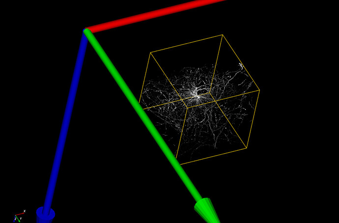
How to translate a volume with changing the data

Hi,

I need to translate my volume in the rendering space, and I need to change the whole underlying data, not just showing the volume at the desired coordinate. My volume data is stored in a vtkImageAlgorithm class (vtkExtractVOI or vtkImageAppend, depending on the situations). Then I use vtkImageChangeInformation to SetOutputOrigin to replace my volume at the desired location. But it turns out to be the same as calling SetPosition at the rendering level, which means that there is no change done to the data, only visualization. Is there any function that does what I want? What is the proper way of doing this?

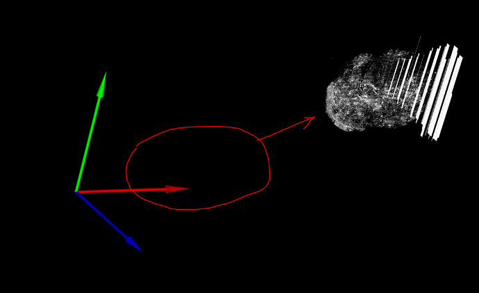
To illustrate what I want to achieve, consider the following picture:


The volume data in this picture still exists in the red oval area. How can I make the data and visualization consistent?

Thanks very much!

Hi Mars, can you show the bounding box of the volume in order to help us understand its position and orientation relative to your axes? You can use vtkOutlineFilter to generate a bounding box that you can add to the scene.

There are essentially three ways to move a volume in VTK, each is distinct from the others:

  1. use SetPosition to change its location in world coordinates
  2. use vtkImageChangeInformation to change its location in data coordinates
  3. use vtkImageReslice to apply a transformation to the voxels themselves

If I could see the volume’s bounding box in your figure, I would have a better idea of which method might be best (especially if I could see whether the volume’s bounding box is aligned with the axes).

Hi David,

As you suggested, this is the volume with bounding box without translation using vtkImageChangeInformation::SetOutputOrigin()

I believe the volume’s bounding box is aligned with the axes.

From your suggestions it sounds like vtkImageReslice is the way I should go because I do need to apply a transformation to the voxels themselves, not just telling the actor to show up somewhere else (don’t know if it’s a right way to say, I’m still a vtk newbie here…). Could you please advice me how to do it?

Thank you so much in advance!

Do you want to move the object’s voxels to the new position, but keep the corner of the bounding box at the corner of your axes? That would require expanding the bounding box by a lot. That’s all possible with vtkImageReslice, but I’m not sure if that’s what you really want to do.

No, I don’t want to keep the bounding box in the same place. I need the bounding box to move wherever the voxels go.

In that case, using vtkImageChangeInformation to adjust the Origin seems to be the best choice. But you said that didn’t work for you… can you explain how you came to that conclusion?

Yes.

I use vtkCamera::GetCompositeProjectionTransformMatrix() to implement a function that allows users to use mouse click to pick up the most probable point. In this case, the most probable point is the voxel with the strongest intensity among all points that share the same homogeneous coordinate with the mouse click. So it should be at some depth in the volume. My end users rely on this function to jump into higher resolution of the desired neighborhood of the volume.

However, it results in error after I used vtkImageChangeInformation because the data doesn’t move along. In fact, I get to jump to the higher resolution by blindly clicking on the blank red oval area in my first picture. That means the data stays where it was.

The CompositeProjectionTransformMatrix maps world coordinates to view coordinates. So in your code, you would also have to map data coords to world coords, and (i,j,k) voxel indexes to data coords. In other words, if you’re thinking about the problem from a computer vision perspective, you will have to adjust your approach. In VTK, the camera transform is just one of many transforms that you have to account for.

The VTK Textbook provides a good description of VTK’s coordinate systems, even though it has gotten a bit out of date.

I understand what you’re saying. But here’s something I have noticed:

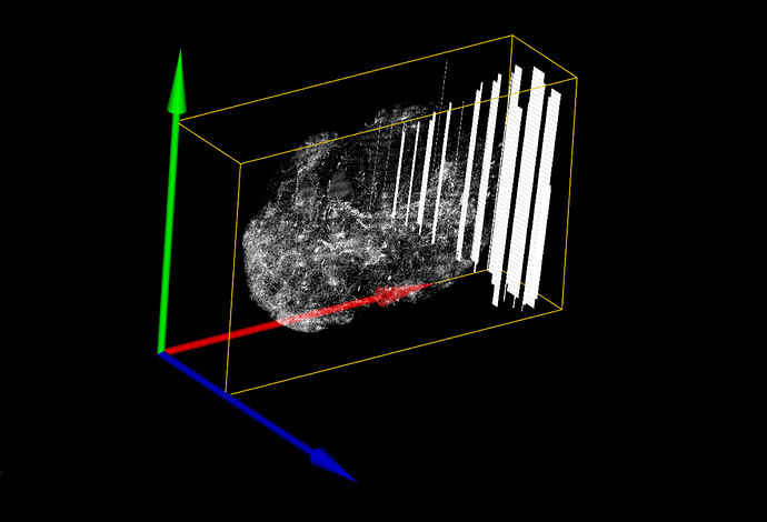
My application is required to assemble a number of smaller volumes to form one single big volume (using vtkImageAppend), and then crop a VOI out of the assembled volume (using vtkExtractVOI). When I show the VOI in the rendering space, it always maintains some gaps to axes, and those gaps are not always the same. Further examination shows that the gap is exactly the distance from the border of the assembled volume to where I cut the VOI. But I didn’t tell the VOI to change its position before rendering them. It seems like the data remains in the same position as it was in the assembled volume (shown in the picture below is a cropped out VOI, and you can see there’s gap to the axes):

I suppose that the cropped VOI maintains the same data coords to world coords mapping as in the original assembled volume. Is there a way I can manipulate this mapping inside a vtkImageAlgorithm object?

It’s a bit tricky to use vtkExtractVOI, because when it crops the volume, it also changes the indexing. Take this simple example in Python:

a = vtkImageData()
a.SetDimensions(100,100,100)
a.AllocateScalars(VTK_UNSIGNED_CHAR,1)

v = vtkExtractVOI()
v.SetInputData(a)
v.SetVOI(25,50,25,50,25,50)
v.Update()

# cropped output
b = v.GetOutput()
b.GetExtent()
(25, 50, 25, 50, 25, 50)
b.GetOrigin()
(0, 0, 0)

The vtkExtractVOI filter has changed the indexing of the volume so that the indexing starts at i=25,j=25,k=25. In order to adjust the volume so that the indexing starts at zero, use vtkImageChangeInformation like this:

c = vtkImageChangeInformation()
c.SetInputData(b)
c.SetOutputExtentStart(0,0,0)
c.Update()

c.GetOutput().GetExtent()
(0, 25, 0, 25, 0, 25)
c.GetOutput().GetOrigin()
(0.0, 0.0, 0.0)

Note that SetOutputExtentStart() and SetOutputOrigin() have complementary effects: they do similar things, but in different coordinate systems. The best way that I can explain it is this:

  • Changing the Extent changes how the volume’s voxels are indexed
  • Changing the Origin (and Spacing and Direction) change how the indices map to what we call VTK’s “Data Coordinates” (some people prefer to call them “Physical Coordinates”)

For convenience, the vtkImageData method GetIndexToPhysicalMatrix() will return a matrix that can be used to map from the i,j,k indices to the Data Coordinates.

I’m pretty sure that vtkImageChangeInformation is the filter that you want to use, and if you’re using it after vtkExtractVOI, you might have to change both the Origin and the Extent of the volume in order to make things work the way you expect.

The mapping from Data Coordinates to World Coordinates is controlled by the vtkProp3D class (this is the base class for vtkActor, vtkVolume, etc). Only subclasses of vtkProp3D can adjust the mapping from Data to World. With these classes, use GetMatrix() to get the 4x4 matrix that maps from Data Coordinates to World Coordinates.
1 Like

Sorry for the late reply. I used vtkImageChangeInformation with SetOutputExtentStart() and it worked nicely! I thought it didn’t work for me in the beginning was because my code was querying one of my data holder object (vtkImageAlgorithm) that wasn’t translated - hence getting intensity readings from the blank area.

Thank you again for your help!