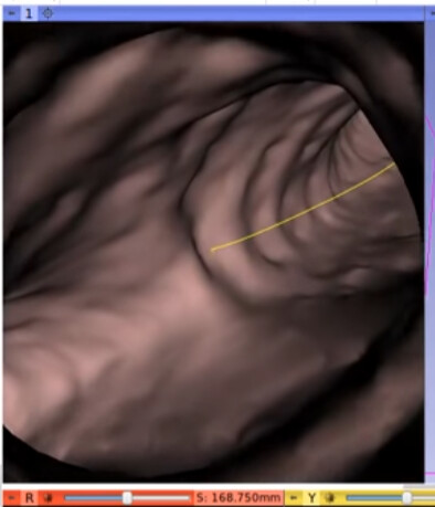
So here is an example of Endoscope feature of 3D Slicer:
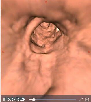
And here is an example from Endosize:
My Question is:
If I wanna do endoscope by VtkVolume, what should I be Awared of?
(I tried some vtkVolume examples, it can do so much but as I zoom in to the position that is inside the aorta it display all white)
To define a camera you need to define the viewUpDirection, the cameraPosition, the cameraFocalPoint and the cameraViewAngle. Ie. On your last picture I think the problem is there not a correct definition of camera position and focalPoint
I would suggest you achieve an example of your visualization on Slicer and then port it to vtk as Slicer a lot of time just exposes vtk API, although a lot is also simplified
There are the endoscopy module on Slicer and volumerendering module. Both can be used to achieve what your picture shows.
For example: you can create the cameraPath on Slicer and save it and then use it on vtk for the same rendered CT.
I would suggest you divide your code on components (small example scripts), customize them and then integrate them. This way you can take advantage of the vtk examples repository.
Materially, you will need a contrasted CT as it’s easier to work with because of the higher HU value contrast that makes it easier to define a useful opacityMapping (pieceWise function)
Thanks for your reply.
As for the camera, I am pretty sure I have full control of camera position and focal point since it works well when I use Mesh Actor instead of volume as background aorta.
I am pretty interested in the camera Path and Volume Rendering module you mentioned. I might do some doc read and try slicer module but at the end I would like to achieve aorta initerior volume rendering without those modules.
I am also interested in the camera path? Does camera path means the center line of arota?
In my thought:
the camera path means the center line of arota: points [100], should camera focal point = points[i], camera position = points[i] + normal? Then, the camera is moved by updating i from 0 to n. Is my though correct?
Then another possible problem might be a not well-defined transfer function having a mind the camera is inside the vessel.
For medical applications, Slicer have a lot of the work already done so I would suggest trying it to get your endoscopic visualization first, you may learn why your use case it’s not working. (i.e. you can install SlicerHeart extension to use it’s intravascular preset (that is the definition of the color and opacity transfer functions)).
A curve can be created by one of VMTK extension’s algorithm or it can be created manually by the user and then it is used to create the camera path.
If you were an expert user of Slicer setting up an initial intravascular visualization should take 5minutes.
Most of times the camera path matches the centerline.
I’m not sure but I think the endoscopy module saves a polyline and uses it like this:
Point i is the camera position
Point i+1 is the focal point
Let me try Edge Extraction first, my friend says the reason that the camera can’t capture any interior details is that the GPU Ray cast on normal voxels from DICOM Image, which is made of solid pixels of vein slice. That means the whole volume I got was solid, which make sense.
I am suggested to do edge Extraction so I can have a hollow mask data before continuing the VR work.
Right, thanks for your advice. I tried vtkContourFilter it works well to extract mask polydata for aorta Actor. But volume rendering would not take its output, since its output is vtkPolyData and volume rendering takes vtkImageData.
I tried to convert vtkPolyData result from vtkContourFilter into vtkImageData, but seems vtkGPUVolumeRayCastMapper could not get it right: An empty nothing showed.Maybe my conversion method is wrong?
Here is the example I used for PolyData to imageData Conversion:
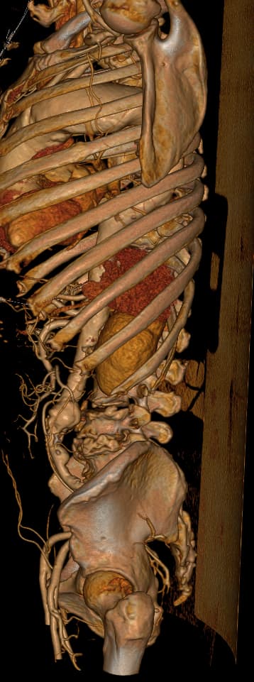
The image is contrasted for sure. It can help create well closed Model Actor in different ways. If it is not required to be more realistic, the Actor version of endoscope already meet demands.
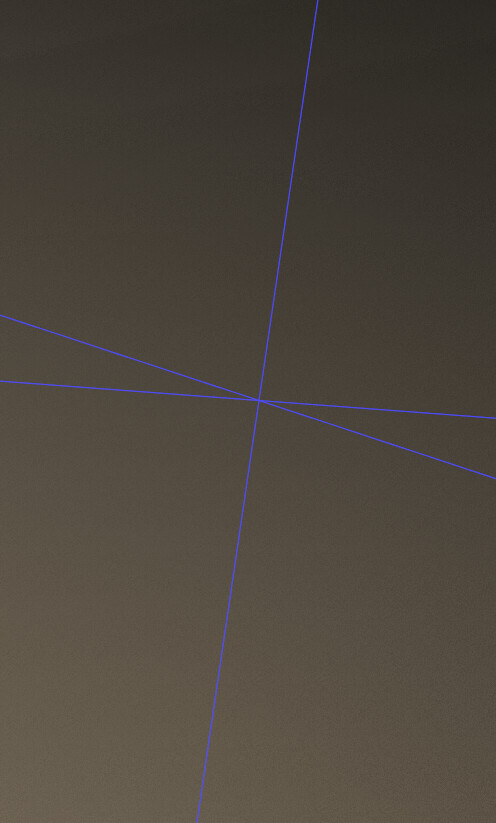
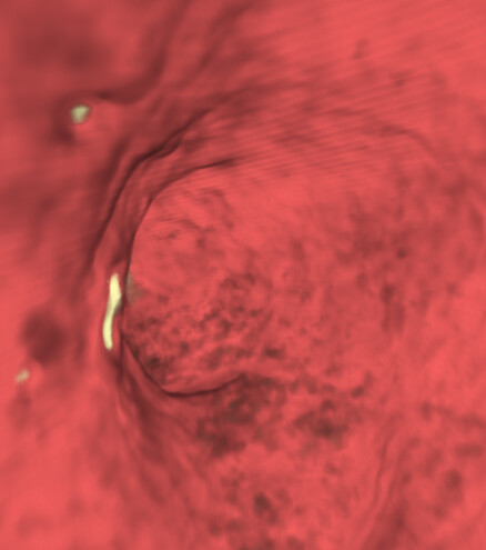
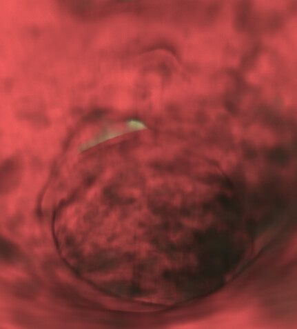
As for opacity transfer function, I have good set of numbers, it can help render volume realistically (picture 3). But the tricky part is: it looks good outside the vein but if I look from inside…(picture 4).
As we do experiments, it become clearer that volumeMapper input image must be filtered into mask image first, similar work like what vtkContourFilter does.
Interesting,how to set two color transfer function for one VolumeProperty? And I dont think we wanna make it look so different from outside to inside.
Even if we dont have any color transfer function, it should render a half-transparent volume in dark grey. You can have a try on volume rendering without any property setting.
You have two options use a 2d transfer function. Or set up a logic to be able to change the 1d transfer function dynamically (e.g. using a button). I’m only sure about the second option
Have you tried prototyping your visualization on Slicer as I suggested earlier?
Thank you. I took your color function advice and got some progress.But the color settings not good and opacity noises apear. Do you think I can get slicer-used property settings?
noises:
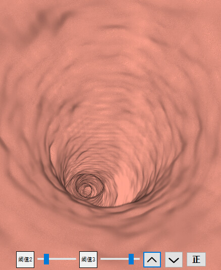
I found that if I set four points for Opacity, Gradient and ColorTransferFunction, I can make it adapt to most different DICOM Images Endoscoping by adding two slider to adjust second and third point index value.