How to visualize vector data using VTK

I am trying to visualize vector data using VTK. From some example I managed to write a code as follows:

#include <vtkActor.h>
#include <vtkDataSetMapper.h>
#include <vtkNamedColors.h>
#include <vtkNew.h>
#include <vtkProperty.h>
#include <vtkRenderWindow.h>
#include <vtkRenderWindowInteractor.h>
#include <vtkRenderer.h>
#include <vtkSmartPointer.h>
#include <vtkXMLUnstructuredGridReader.h>
#include <vtkDataset.h>
#include <vtkCellData.h>
// #include <vtkPointData.h>
#include <vtkLookupTable.h>
#include <vtkUnstructuredGrid.h>
#include <vtkPointData.h>
#include <vtkDataArray.h>
#include <vtkScalarBarActor.h>
#include <vtkCameraOrientationWidget.h>
#include <vtkGlyph3D.h>
#include <vtkArrowSource.h>
#include <vtkConeSource.h>

int main(int argc, char *argv)
{
// parse command line arguments
if (argc < 2)
{
std::cerr << “Usage: " << argv[0] << " Filename(.vtu) e.g. tetra.vtu”
<< std::endl;
return EXIT_FAILURE;
}

std::string filename = argv[1];

// std::string filename =“D:\Study\VTK\VTK-9.2.6-Data\Testing\Data\test.vtu”;
// read all the data from the file
vtkNew reader;
reader->SetFileName(filename.c_str());
reader->Update();

vtkNew colors;
// Create a mapper and actor
vtkNew mapper;
vtkDataSet *dataSet = reader->GetOutputAsDataSet();
dataSet->Print(std::cout);
mapper->SetInputConnection(reader->GetOutputPort());
mapper->ScalarVisibilityOn();
mapper->SetColorModeToMapScalars();
mapper->UseLookupTableScalarRangeOn();
vtkNew actor;
actor->SetMapper(mapper);
actor->GetProperty()->EdgeVisibilityOn();
actor->GetProperty()->SetLineWidth(2.0);
actor->GetProperty()->SetOpacity(0.5);
actor->GetProperty()->SetColor(colors->GetColor3d(“Tomato”).GetData());

//try to generate cell vector:
vtkNew glyph3D;
vtkNew arrowSource;
glyph3D->SetSourceConnection(arrowSource->GetOutputPort());
glyph3D->SetVectorModeToUseVector();
glyph3D->SetInputConnection(reader->GetOutputPort());
glyph3D->SetVectorModeToUseVector();
glyph3D->SetScaleFactor(.8);
glyph3D->Update();

vtkNew glyphMapper;
glyphMapper->SetInputConnection(glyph3D->GetOutputPort());

vtkNew glyphActor;
glyphActor->SetMapper(glyphMapper);

// Create a renderer, render window, and interactor
vtkNew renderer;
vtkNew renderWindow;
renderWindow->AddRenderer(renderer);
vtkNew renderWindowInteractor;
renderWindowInteractor->SetRenderWindow(renderWindow);

// Add the actor to the scene
renderer->AddActor(actor);
renderer->AddActor(glyphActor);
renderer->SetBackground(colors->GetColor3d(“Wheat”).GetData());

//add a xyz
vtkNew widgetCam;
widgetCam->SetParentRenderer(renderer);
widgetCam->On();

// Render and interact
renderWindow->SetSize(640, 480);

renderWindow->Render();
renderWindowInteractor->Start();

return EXIT_SUCCESS;
}

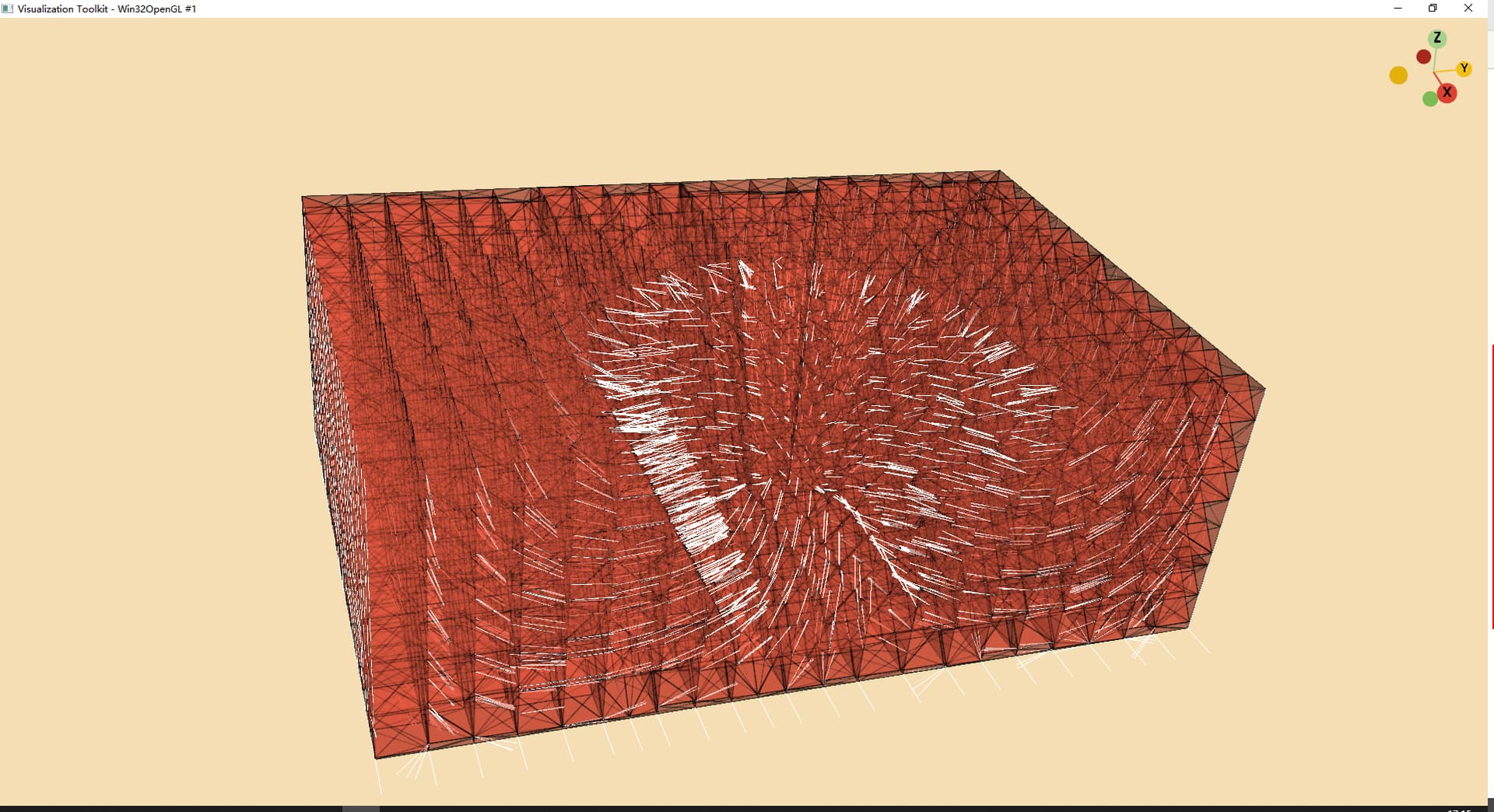
However, the result seemed not as expected:


as we can see, all vectors are directed at X direction.

By the way I am wondering how to watch the inner data of a vtkDataSet? I tried to watch it by visual studio but could not find any valuable information.

I appreciate your explation, thank you.
test.7z (2.7 MB)

The data that printed out is as follows:

vtkUnstructuredGrid (0x1a0df80)
Debug: Off
Modified Time: 293
Reference Count: 1
Registered Events: (none)
Information: 0x1a0c390
Data Released: False
Global Release Data: Off
UpdateTime: 330
Field Data:
Debug: Off
Modified Time: 229
Reference Count: 1
Registered Events: (none)
Number Of Arrays: 0
Number Of Components: 0
Number Of Tuples: 0
Number Of Points: 23406
Number Of Cells: 37830
Cell Data:
Debug: Off
Modified Time: 288
Reference Count: 1
Registered Events:
Registered Observers:
vtkObserver (0x1a089b0)
Event: 33
EventName: ModifiedEvent
Command: 0x1a0c430
Priority: 0
Tag: 1
Number Of Arrays: 1
Array 0 name = Stress
Number Of Components: 6
Number Of Tuples: 37830
Copy Tuple Flags: ( 1 1 1 1 1 0 1 1 1 1 1 )
Interpolate Flags: ( 1 1 1 1 1 0 0 1 1 1 1 )
Pass Through Flags: ( 1 1 1 1 1 1 1 1 1 1 1 )
Scalars: (none)
Vectors: (none)
Normals: (none)
TCoords: (none)
Tensors: (none)
GlobalIds: (none)
PedigreeIds: (none)
EdgeFlag: (none)
Tangents: (none)
RationalWeights: (none)
HigherOrderDegrees: (none)
Point Data:
Debug: Off
Modified Time: 283
Reference Count: 1
Registered Events:
Registered Observers:
vtkObserver (0x1a08a70)
Event: 33
EventName: ModifiedEvent
Command: 0x1a0c430
Priority: 0
Tag: 1
Number Of Arrays: 1
Array 0 name = Displacement
Number Of Components: 3
Number Of Tuples: 23406
Copy Tuple Flags: ( 1 1 1 1 1 0 1 1 1 1 1 )
Interpolate Flags: ( 1 1 1 1 1 0 0 1 1 1 1 )
Pass Through Flags: ( 1 1 1 1 1 1 1 1 1 1 1 )
Scalars: (none)
Vectors: (none)
Normals: (none)
TCoords: (none)
Tensors: (none)
GlobalIds: (none)
PedigreeIds: (none)
EdgeFlag: (none)
Tangents: (none)
RationalWeights: (none)
HigherOrderDegrees: (none)
Bounds:
Xmin,Xmax: (75, 140)
Ymin,Ymax: (50, 150)
Zmin,Zmax: (-10, 25.0011)
Compute Time: 351
Editable: false
Number Of Points: 23406
Point Coordinates: 0x1a162d0
PointLocator: 0
CellLocator: 0
Number Of Pieces: 1
Piece: 0
Ghost Level: 0

Here I have several confusions:

  1. How can I get the Displacement and why it is not in Vectors? (the same issue is for stress, why it is not in vectors?)

  2. When should I use getOutput() vs getOutputPort()? when trying to get some data, I am really confused of the choose of these functions.

  3. As a new leaner, VTK is like a box of many toy building blocks. It is easy to read the example code, however, if I want to customize it myself, I don’t know how to start because I am facing a box of blocks that I am not familiar with. So is there any way to solve this? I know there’s plenty of examples but that could only solve a limited problem.

From the looks of it, the code you posted and the image it produces look right.

If you look at the printout of your data, there are no vectors in the data itself. Maybe start out with a dataset that has vectors or use the vtkRandomAttributeGenerator for generating vectors for each point of your dataset.

GetOutputPort is used when connecting a pipeline of filters before any data is available whereas GetOutput and GetOutputDataObject is to access the data after the pipeline has run.

Start with reading documentation on VTK and looking at examples. Kitware offers training and support as well. See https://www.kitware.com/training/ and https://www.kitware.com/commercial/support/

Hi,

VTK can be a bit overwhelming at first glance, so I recommend taking a look at the VTK primer: VTK Textbook | VTK . You can download its PDF for free.

The first thing to know is that VTK is a pipeline-oriented graphics API, that is, you code a sequence of operations that results in the desired effect. This is an alternative to scene graph-oriented APIs (e.g. OpenInventor, Ogre 3D, etc.). Both API types serve to abstract lower-level, state-keeping graphics APIs (normally OpenGL), the so-called graphics back end.

take care,

PC

1 Like

Thanks Sankhesh.
As for question 1, I just switched from vtkGlyph3D to vtkGlyph3DMapper (I deleted all vtkGlyph3D code, only using vtkGlyph3DMapper ) using the following code:

  //delete all code which contains vtkGlyph3D 
  vtkNew<vtkGlyph3DMapper> glyphMapper;
  // glyphMapper->SetSourceConnection(arrowSource->GetOutputPort());
  glyphMapper->SetInputConnection(reader->GetOutputPort());
  glyphMapper->SetOrientationArray("Displacement");
  glyphMapper->SetScaleFactor(5.0);

  vtkNew<vtkActor> glyphActor;
  glyphActor->SetMapper(glyphMapper);

, and the result is:


which shows the vector direction. Althouth it is still different from the paraview, at least it shows the direction.

Then I looked up the official manual for vtkGlyph3DMapper and the manual says that it " Do the same job than vtkGlyph3D but on the GPU." So I think vtkGlyph3D should have a similar function as this, but I could not find it out.

And the above example is also an example of my 3rd question, as I can easily use

glyphMapper->SetOrientationArray(“Displacement”);

but I could not find a similar one for vtkGlyph3D :joy: I think this is the hardest thing for me to learn vtk, that is, I must remember a lot of rules which has a specific usage for a specific class…

Hi Paulo, I’ve just tried to add “Displacement” array into Vectors and then I managed to get the displacement by using vtkGlyph3D.
I just added

data->SetActiveVectors(“Displacement”);

In my original code and the result is:

As you can see, the displacement vector almost look the same as the Paraview result, however, It still shows some inconsistency at the bottom of the block(I also used vtkGlyph3DMapper as I mentioned in my reply to Sankhesh, and this also has the same inconsistency) which Paraview does not have.

I think most of the problems have now been solved, but the only remaining one is the inconsistency displacement vector. I think this should be some error but both my two ways( vtkGlyph3D as well as vtkGlyph3DMapper) has this same error. I don’t know why.

Update: By adding

glyph3D->SetScaleModeToScaleByVector();

I got the same result as Pareview.

1 Like

Please, mark it as solution so others with the same problem can find quickly how to solve it. Thanks.