Mesh voxelization with two colours

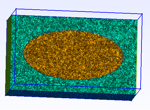
I have created a volumetric mesh using gmsh toolkit as you can see a clipping view of it below. It has an ellipsoid inside of a box. I have used two physical groups one is to hold the data for ellipsoid and the other group is to hold the whole 3D volumetric mesh using gmsh. I’m able to export this mesh as a .vtk file using the gmsh GUI.

Now I want to convert this whole volumetric mesh into a 3D CT like image (as a nifti image) by using two separate colours for the ellipsoid region as well as the region in between box and the ellipsoid.

How can I do that ? Is there a way to identify these two regions to colour them appropriately in VTK? If so can you please elaborate with an example ?

volumetric_mesh

You can use vtkProbeFilter for this. You should be able to find good examples for using this filter in VTK tests and VTK Examples website.

I just implemented with probe filter as you can see below. But when I try to save the output of the vtkProbeFilter as nifiti image it gives an error. How can I write the output of the probe filter to the nifti image ?

vtkSmartPointer<vtkUnstructuredGridReader> reader =
	vtkSmartPointer<vtkUnstructuredGridReader>::New();
reader->SetFileName(ref_volumetric_mesh_path.c_str());
reader->Update();

vtkSmartPointer<vtkUnstructuredGrid> source = reader->GetOutput();

vtkSmartPointer<vtkImageData> input =
	vtkSmartPointer<vtkImageData>::New();

input->SetDimensions(60, 60, 100);
input->SetSpacing(0.5, 0.5, 0.5);
input->SetOrigin(0.0, 0.0, 0.0);

// Interpolate PointData from the mesh to the points of the Image
vtkSmartPointer<vtkProbeFilter> filter = vtkSmartPointer<vtkProbeFilter>::New();
filter->SetSourceData(source);
filter->SetInputData(input);
filter->Update();

vtkSmartPointer<vtkNIFTIImageWriter> writer =
	vtkSmartPointer<vtkNIFTIImageWriter>::New();
writer->SetFileName(ref_volumetric_mesh_voxelized_path.c_str());

writer->SetInputData(filter->GetOutput());
writer->Write();

Should I use vtkPolyDataToImageStencil and vtkImageStencil for that ? If so how ? Can you please help me on this matter?

And also I try to write the output as a .mhd file, but the output file is empty and only contains the header, see below. Am I doing something wrong here ? Please help me on this matter. Thank you very much for your time and consideration.

ObjectType = Image
NDims = 3
BinaryData = True
BinaryDataByteOrderMSB = False
CompressedData = True
TransformMatrix = 1 0 0 0 1 0 0 0 1
Offset = 0 0 0
CenterOfRotation = 0 0 0
ElementSpacing = 0.5 0.5 0.5
DimSize = 60 60 100
AnatomicalOrientation = ???
ElementType = MET_DOUBLE
ElementDataFile = example_gen_image_vol.zraw

Yes, that’s a good approach, too. For each material, extract cells using vtkThreshold filter, get outer surface using vtkGeometryFilter, and fill the image using vtkImageStencil.

Thank you very much for your reply. But my main concern is why the above code was not able to produce the correct output ? Did I do something wrong there ? wrong with the input data or source data for probe filter?

I just added these two line when reading the unstructured grid.
reader->ReadAllVectorsOn();
reader->ReadAllScalarsOn();

Added below line of code to the vtkImageData object.
input->AllocateScalars(VTK_FLOAT, 2);

And then add the below two lines to the vtkProbeFilter.
filter->SetPassCellArrays(true);
filter->SetPassPointArrays(true);

But, I’m unable to produce the correct output image. Did I miss any steps here ?

If you have material ID in point data then probe filter should provide a good output, you just need to copy the point data of the structured grid into point data of a vtkImageData (I don’t think there is a filter that does this, but you can access the arrays and copy the array content manually, you just need to make sure the number and spacing of the points match).

If you have material ID specified in cell data then it is probably better to use the surface-based approach: extract each material by threshold filter, get its outer surface using geometry filter, and rasterize it into an image using image stencil.

I have implemented the second approach that you mentioned yesterday since the physical tags (1 and 2) are saved in the CELL_DATA field (see the code below). Then I plot the middle slice of the generated nifiti image and now it contains both the box and the ellipsoid inside it.

But the ellipsoid position is not centered inside the box as you can see in the attached image. Did I miss some steps here?

I highly appreciate your willingness to resolve this issue as well.

 vtkSmartPointer<vtkUnstructuredGridReader> reader =
        vtkSmartPointer<vtkUnstructuredGridReader>::New();
    reader->SetFileName(ref_volumetric_mesh_path.c_str());
    reader->ReadAllVectorsOn();
    reader->ReadAllScalarsOn();
    reader->Update();

    // Extract ellipsoid mesh
    vtkSmartPointer<vtkThreshold> threshold_ellipsoid =
        vtkSmartPointer<vtkThreshold>::New();
    threshold_ellipsoid->SetInputData(reader->GetOutput());
    threshold_ellipsoid->SetInputArrayToProcess(0, 0, 0, vtkDataObject::FIELD_ASSOCIATION_CELLS, vtkDataSetAttributes::SCALARS);
    threshold_ellipsoid->ThresholdByLower(1);
    threshold_ellipsoid->Update();
    //Ellipsoid mesh
    //threshold_ellipsoid->GetOutput();

    // Extract box mesh without ellipsoid
    vtkSmartPointer<vtkThreshold> threshold_box =
        vtkSmartPointer<vtkThreshold>::New();
    threshold_box->SetInputData(reader->GetOutput());
    threshold_box->SetInputArrayToProcess(0, 0, 0, vtkDataObject::FIELD_ASSOCIATION_CELLS, vtkDataSetAttributes::SCALARS);
    threshold_box->ThresholdByUpper(2);
    threshold_box->Update();
    //Box mesh
    //threshold_box->GetOutput();

    vtkSmartPointer<vtkGeometryFilter> ellipsoidGeometryFilter =
        vtkSmartPointer<vtkGeometryFilter>::New();
    ellipsoidGeometryFilter->SetInputData(threshold_ellipsoid->GetOutput());
    ellipsoidGeometryFilter->Update();

    vtkSmartPointer<vtkPolyData> polyDataForEllipsoid = ellipsoidGeometryFilter->GetOutput();

    vtkSmartPointer<vtkGeometryFilter> boxGeometryFilter =
        vtkSmartPointer<vtkGeometryFilter>::New();
    boxGeometryFilter->SetInputData(threshold_box->GetOutput());
    boxGeometryFilter->Update();
    vtkSmartPointer<vtkPolyData> polyDataForBox = boxGeometryFilter->GetOutput();

    vtkSmartPointer<vtkImageData> ellipsoidImage =
        vtkSmartPointer<vtkImageData>::New();
    double ellipsoidBounds[6];
    polyDataForEllipsoid->GetBounds(ellipsoidBounds);
    double ellipsoidSpacing[3]; // desired volume spacing
    ellipsoidSpacing[0] = 0.5;
    ellipsoidSpacing[1] = 0.5;
    ellipsoidSpacing[2] = 0.5;
    ellipsoidImage->SetSpacing(ellipsoidSpacing);

    int ellipsoidDim[3];
    for (int i = 0; i < 3; i++)
    {
        ellipsoidDim[i] = static_cast<int>(ceil((ellipsoidBounds[i * 2 + 1] - ellipsoidBounds[i * 2]) / ellipsoidSpacing[i]));
    }

    ellipsoidImage->SetDimensions(ellipsoidDim);
    ellipsoidImage->SetExtent(0, 59, 0, 59, 0, 99);

    double ellipsoidOrigin[3];
    ellipsoidOrigin[0] = ellipsoidBounds[0] + ellipsoidSpacing[0] / 2;
    ellipsoidOrigin[1] = ellipsoidBounds[2] + ellipsoidSpacing[1] / 2;
    ellipsoidOrigin[2] = ellipsoidBounds[4] + ellipsoidSpacing[2] / 2;
    ellipsoidImage->SetOrigin(ellipsoidOrigin);

    ellipsoidImage->AllocateScalars(VTK_UNSIGNED_CHAR, 1);
    // fill the image with foreground voxels:
    unsigned char ellipsoidInval = 100;
    vtkIdType ellipsoidCount = ellipsoidImage->GetNumberOfPoints();
    for (vtkIdType i = 0; i < ellipsoidCount; ++i)
    {
        ellipsoidImage->GetPointData()->GetScalars()->SetTuple1(i, ellipsoidInval);
    }

    vtkSmartPointer<vtkPolyDataToImageStencil> pol2stenc =
        vtkSmartPointer<vtkPolyDataToImageStencil>::New();

    pol2stenc->SetInputData(polyDataForEllipsoid);
    pol2stenc->SetOutputOrigin(ellipsoidOrigin);
    pol2stenc->SetOutputSpacing(ellipsoidSpacing);
    pol2stenc->SetOutputWholeExtent(ellipsoidImage->GetExtent());
    pol2stenc->Update();

  
    //Box vtkImage
    vtkSmartPointer<vtkImageData> boxImage =
        vtkSmartPointer<vtkImageData>::New();
    double boxBounds[6];
    polyDataForBox->GetBounds(boxBounds);
    double boxSpacing[3]; // desired volume spacing
    boxSpacing[0] = 0.5;
    boxSpacing[1] = 0.5;
    boxSpacing[2] = 0.5;
    boxImage->SetSpacing(boxSpacing);

    int boxDim[3];
    for (int i = 0; i < 3; i++)
    {
        boxDim[i] = static_cast<int>(ceil((boxBounds[i * 2 + 1] - boxBounds[i * 2]) / boxSpacing[i]));
    }

    boxImage->SetDimensions(boxDim);
    boxImage->SetExtent(0, 59, 0, 59, 0, 99);

    double boxOrigin[3];
    boxOrigin[0] = boxBounds[0] + boxSpacing[0] / 2;
    boxOrigin[1] = boxBounds[2] + boxSpacing[1] / 2;
    boxOrigin[2] = boxBounds[4] + boxSpacing[2] / 2;
    boxImage->SetOrigin(boxOrigin);

    boxImage->AllocateScalars(VTK_UNSIGNED_CHAR, 1);

    unsigned char boxInval = 255;
    vtkIdType boxCount = boxImage->GetNumberOfPoints();
    for (vtkIdType i = 0; i < boxCount; ++i)
    {
        boxImage->GetPointData()->GetScalars()->SetTuple1(i, boxInval);
    }


    vtkSmartPointer<vtkImageStencil> imgstenc =
        vtkSmartPointer<vtkImageStencil>::New();
    imgstenc->SetInputData(ellipsoidImage);
    imgstenc->SetStencilConnection(pol2stenc->GetOutputPort());
    imgstenc->ReverseStencilOff();
    imgstenc->SetBackgroundInputData(boxImage);
    imgstenc->Update();

    vtkSmartPointer<vtkNIFTIImageWriter> writer =
        vtkSmartPointer<vtkNIFTIImageWriter>::New();
    writer->SetFileName(ref_volumetric_mesh_voxelized_path.c_str());
    writer->SetInputData(imgstenc->GetOutput());
    writer->Write();

The output image slice.
rasterize_image_after_geom_filter