I am visualizing a DICOM CT dataset using vtk / Activiz. Now I want to place objects (e.g. a sphere for testing) using the DICOM coordinate space as defined by Image Position Patient / Image Orientation Patient. To this end I use the following code (I hardcoded some values to match my sample dataset, which is a coronal MPR series):
                lMatrix.SetElement(0, 0, 1);
                lMatrix.SetElement(0, 1, 0);
                lMatrix.SetElement(0, 2, 0);
                lMatrix.SetElement(1, 0, 0);
                lMatrix.SetElement(1, 1, 0);
                lMatrix.SetElement(1, 2, -1);
                lMatrix.SetElement(2, 0, 0);
                lMatrix.SetElement(2, 1, 1);
                lMatrix.SetElement(2, 2, 0);
                lMatrix.Transpose();
                lVolume.SetUserMatrix(lMatrix);

                lVolume.SetPosition(-157.69201, 46.0664062, 192.633416);

                var sphereSource = new vtkSphereSource();
                sphereSource.SetRadius(5.0);
                // Make the surface smooth.
                sphereSource.SetPhiResolution(100);
                sphereSource.SetThetaResolution(100);

                var mapper = new vtkPolyDataMapper();
                mapper.SetInputConnection(sphereSource.GetOutputPort());

                var actor = new vtkActor();
                actor.SetUserMatrix(lMatrix);
                // place the sphere in the middle of the upper volume bounds
                actor.SetPosition(-157.69201 + 0.5*512*0.61, 46.0664062 + 0.5*512*0.61, 192.633416);
                actor.SetMapper(mapper);

                var axes = new vtkAxesActor();
                axes.SetTotalLength(350, 350, 350);
                axes.SetShaftTypeToCylinder();
                axes.SetCylinderRadius(0.01);


                Renderer.AddActor(actor);
                Renderer.AddActor(axes);
                Renderer.AddVolume(lVolume);
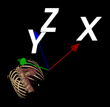
In this code I want to place the sphere at the middle of the upper bounds of the volume. However, it seems that the Y and Z axis is flipped (see screenshot). It’s more like the sphere is displayed in the middle of the first coronal slice. I assume that I’m understanding something incorrectly, can someone please help me?
The axes I am visualizing are correctly adjusted, so the volume is transformed correctly.
If you are sure that in all the images that you ever want to load image slices are equally spaced then you can use vtk-dicom to read the DICOM series into a vtkImageData.
vtk-dicom also provides the IJK to LPS transform (PatientMatrix) that you can use to set your lmatrix. Also check out examples in vtk-dicom.
Thanks, however I can’t use vtk-dicom as I already have all image data and other parameters in memory and can’t afford to load them again with another library.
Nonetheless I figured it out. First, the transformation on the sphere is obviously wrong, as the volume is already transformed. Second, I ended up with the same affine matrix as the one in vtk-dicom, ie. the orientation transform followed by position translation. If I use SetPosition as in the example, I end up getting a different transformation matrix, where the position translation is done first followed by orientation transformation.
It is no problem that you use the VTK built-in DICOM reader, as there might be a chance that it fulfills requirements of your project. However, it is important to describe limitations of this reader to make it clear for anyone who comes across this topic that compared to vtk-dicom the built-in DICOM reader has many limitations - including some very severe ones:
The biggest trouble with VTK’s built-in DICOM reader that it does not sort and groups frames correctly. You can just get completely messed up images without any warnings. vtk-dicom does things quite nicely - see it sorter implementation, which does not do anything fancy, just has the basic features that are needed to read the supported image types.
Computation of spacing between slices is extremely fragile (if a few slice is missing or the slices are not equally spaced - all valid DICOM - then you get a distorted image without a warning)
Tilted-gantry acquisitions are loaded as a distorted image
Many images cannot be loaded, because they use the enhanced multi-frame storage formats, image compression, non-Latin1 text encoding.
The code is not optimized for performance either and does not support DICOMDIR, which also means that your application will be slower if you use the built-in DICOM reader.
The code is barely tested. Users do not complain about the built-in DICOM reader because nobody (at least none of the serious medical image computing application use it). Non-regression testing of the DICOM classes in VTK is extremely limited (just done on a single CT slice and a tiny fMRI stack).
It would be better to remove the DICOM classes from VTK because it is not up to VTK’s quality standards and users may mistakenly think that they can trust them. Instead, medical image computing users can enable vtk-dicom remote module when they configure VTK.