Hi there,
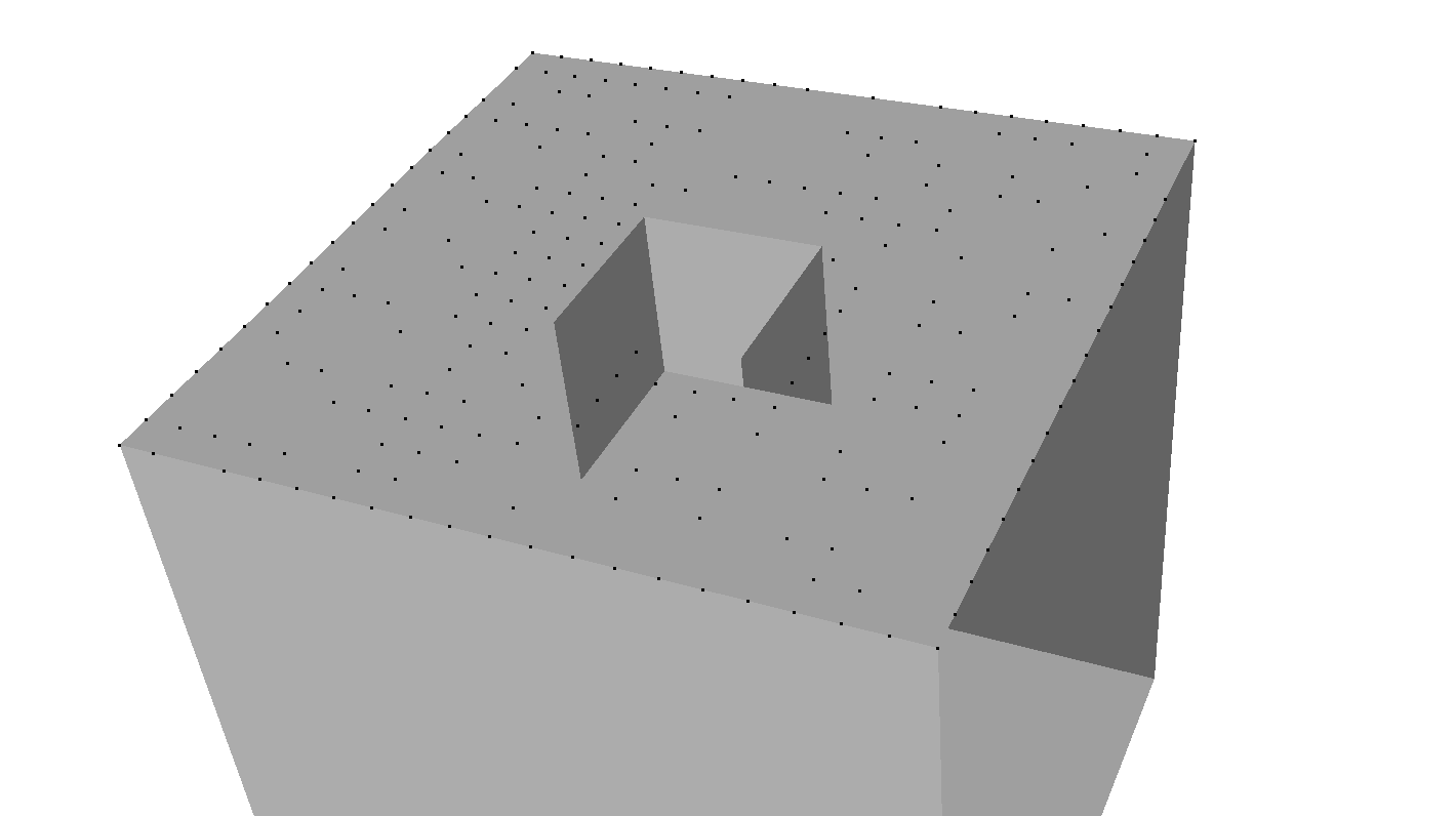
I’m loading STL files which come from various CAD Software. My goal is to create a grid of points in the x,y-plane at the top of the STL. I do this by creating the pattern according to the STL’s bounds and getting rid of the unwanted points by using vtkSelectEnclosedPoints.
There a some points missing which are clearly part of the STL (resolution is 1 point per mm):
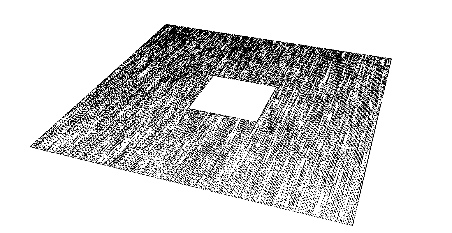
If I increase the resolution blanks are getting filled - resolution 12 points per mm:
But still it is not an equidistant grid like I would expect. Here is the code that is doing the picking of points:
  for (vtkIdType i = 0;
       i < selectEnclosedPoints->GetOutput()->GetNumberOfPoints(); i++) {
    if (selectEnclosedPoints->IsInside(i) == 1) {
      double pt[3];
      selectEnclosedPoints->GetOutput()->GetPoint(i, pt);
      PointT pclPt;
      pclPt.x = pt[0];
      pclPt.y = pt[1];
      pclPt.z = pt[2];
      cloud_out->push_back(pclPt);
    } else {
      double pt[3];
      selectEnclosedPoints->GetOutput()->GetPoint(i, pt);
      qDebug() << "Point: " << pt[0] << " " << pt[1] << " " << pt[2];
    }
  }
The cube shown is centered and has the dimension 20x20x20mm. For example with 1 point per mm the point [-9, -8, 20] is not “inside” although it should be. What am I missing? Thanks!
Sadly I’m too new to attach the stl in question.