I have no idea what version of vtkCookieCutter is in PV 5.9.1, but since the latest (significant) changes to vtkCookieCutter were just made a week or so ago I suspect that it is an older version.
It definitely is outdated. However, downloading the most recent version from the repository left me with a PV build emitting errors, so there seem to be dependencies that are not correct any more. In other words: Some porting work would be required first…
On the other hand I understand you in a way that it might even be worthwile!?
One nice feature of that cutter would be the fact that it handles also cell and point data in e reasonable way, i.e. interpolating, which gave me the idea that I should first flatten the surface, but write the z coordinates into a temporary point attribute and let it be handled in exactly that way. After a successful cookie cutting process, I could simply put the z values back in and remove the temporary attribute.
However, no idea whether that feature is already in that old cookie cutter, and without any cutting success, it is not important either.
Well, one day I am planning to follow the PV versions anyway, but I realized that permanently doing it is a real pain and not really worth it…
Paraview 5.10 is available for download here https://www.paraview.org/download/ if that helps.
Now I have downloaded the vtkCookieCutter from the current master, and instead of integrating it into my underlying ParaView, I renamed the files and the class, I just integrated it into my own custom code. With this, I was able to get it into my code without porting the entire ParaView base.
The result was again like my last screenshot above: not much to do with punching a hole into a topo…
My guess is now that I must be doing still something completely wrong, so I tried the thing with a very very trivial case: a competely flat “topo” at level 0, consisting of only two triangles, and a “cutter” or “loop” that is again only one single triangle, as well at level 0. Result? I am indeed getting a triangle cut out of my “topo”. Only shortcoming: I get the triangle, not the topo with a triangle hole. (Ok, if I am really cutting cookies, I also want toe cookies, not the surrounding  ).
).
Learning #1: I have to find out how to “explain” that I want the same thing inverted!
Question - to be tried out: either it is a question of reversing the sense of rotation of the triangle, or it is a question of providing another polygon that is “outside” my topo and that “cuts” the topo as a whole, in the first place.
These are my “super mini topo” and “super mini cutter”:
miniminibound.vtp (2.3 KB)
miniminitopo.vtp (3.5 KB)
And this is the code that was supposed to punch the hole. Note: I write such functions that are then the only one called within the RequestData function of my custom filter.
int vtkAtgTopoCookieCutter::cutWithCookieCutter(vtkInformationVector** inputVector,
                                                vtkInformationVector* outputVector)
{
    // get the input and output
    // note that the cutter can be either one or several polygons or
    // a block model (unstructured grid)
    vtkPolyData* input = vtkPolyData::GetData(inputVector[0], 0);
    vtkPointSet* cutterPSet = vtkPointSet::GetData(inputVector[1], 0);
    vtkPolyData* output = vtkPolyData::GetData(outputVector, 0);

    // here we would have to handle the block models etc. and do some checking
    // right now we assume that everything is fine with the input...
    //77// todo

    vtkPolyData* cutter = vtkPolyData::SafeDownCast(cutterPSet);
    if(nullptr == cutter)
    {
        vtkOutputWindowDisplayWarningText("");
        output->ShallowCopy(input);
        return 1;
    }

    // a temporary shallow copy for adding another point attribute and as input for
    // the cookie cutter filter
    vtkSmartPointer<vtkPolyData> tempSurface = vtkSmartPointer<vtkPolyData>::New();
    tempSurface->ShallowCopy(input);

    // add a point attribute containing the altitudes that we are going to flatten away
    vtkSmartPointer<vtkDoubleArray> alti = vtkSmartPointer<vtkDoubleArray>::New();
    alti->SetName("_TEMP_ALTITUDES_");
    vtkPoints* points = tempSurface->GetPoints();
    alti->SetNumberOfTuples(points->GetNumberOfPoints());
    for(vtkIdType p = 0; p < points->GetNumberOfPoints(); ++p)
    {
        double pt[3];
        points->GetPoint(p, pt);
        alti->SetValue(p, pt[2]);
        pt[2] = 0.;
        points->SetPoint(p, pt);
    }
    tempSurface->SetPoints(points);
    tempSurface->GetPointData()->AddArray(alti);

    // flatten also the cutter and convert it into a polygon at the same time
    vtkSmartPointer<vtkPolyData> flatCutter = vtkSmartPointer<vtkPolyData>::New();
    flatCutter->Allocate();
    vtkSmartPointer<vtkIdList> ids = vtkSmartPointer<vtkIdList>::New();
    points = cutter->GetPoints();
    for(vtkIdType p = 0; p < points->GetNumberOfPoints(); ++p)
    {
        double pt[3];
        points->GetPoint(p, pt);
        pt[2] = 0.;
        points->SetPoint(p, pt);
        ids->InsertNextId(p);
    }
    flatCutter->SetPoints(points);
    flatCutter->InsertNextCell(VTK_POLYGON, ids);

    // now let's get hold of the cookie cutter filter
    vtkSmartPointer<vtkCookieCutterAtg> ccutter = vtkSmartPointer<vtkCookieCutterAtg>::New();
    ccutter->SetInputData(tempSurface);
    ccutter->SetLoopsData(flatCutter);
    ccutter->SetPointInterpolationToMeshEdges();
    ccutter->Update();
    output->ShallowCopy(ccutter->GetOutput());

    // now the previously removed and then interpolated altitudes should be put back
    // into all points
    //77// todo

    return 1;
}
Below the results with the “minimini” topo and cutter, then again the result with my “original” problem:

[Question to myself: Why am I still trying to get this cookie cutter working? Because when reading the documentation it sounds like it is exactly the thing that I am looking for!!]
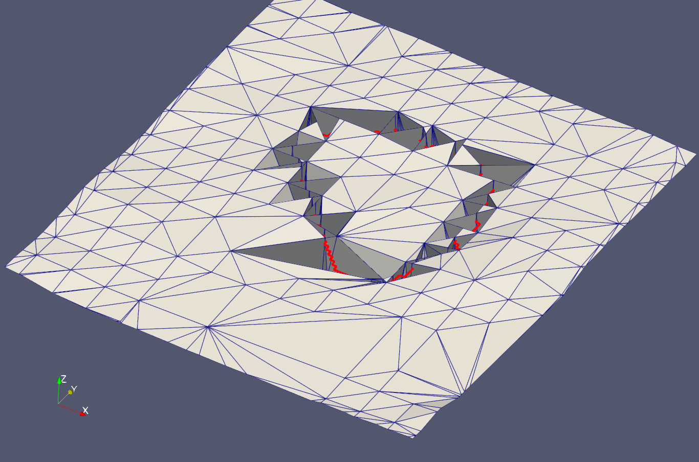
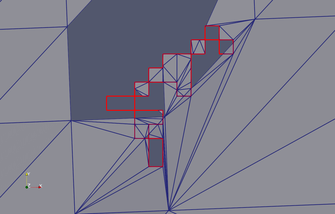
On my other “working thread”, i.e. realizing the variant where I have to 1) interpolate all the “boundary” points to the correct level within the “topo surface”, 2) remove all triangles from the “topo” that are inside or along the boundary line (and eventually triangulate and merge the “ring” between “topo hole” and boundary polygon), I realize also that I have another intermediate problem to solve: see below.
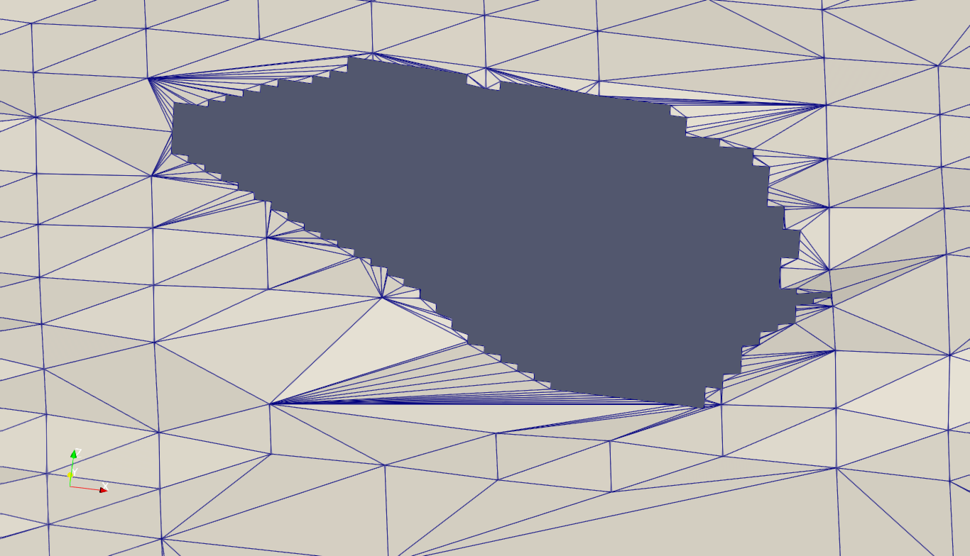
The point is: vtkExtractGeometry works fine, but it looks like it’s understanding of “cells outside the boundary” is: cells where all points are outside the boundary. However, in the lower right corner it is obvious that there are two triangles that fall into this definition, but still go through part of the “inner” area. It looks like they will require special handling! [Yes, this can be done, but it is the moment where I wish that the “cookie cutter” would simply do what I expect ;-)]
Just out of interest. Why is your surface mesh so irregular?
Let’s try this. I thought vtkCookieCutter had an inside/out mode, but that was a MR I saw that had not made it into VTK master yet.
There is another filter: vtkImprintFilter, that is much faster, and can do the same thing as cookie cutter if configured properly. A script is attached, it seems to do what you want. Note that I had to hack a projection to the z-plane, and also the boundarylines had to be connected to form a loop (they were separate lines - the final loop shown in red). This is a recent filter and we are actively improving the numerics, so this is good test data, and if you see problems please let me know. And BTW, vtkImprintFilter does copy/interpolate point and cell data.

imprint.py (2.02 KB)
@Todd: Well, this is a “demo topo” that was intentionally done in a somewhat “sloppy” way because I do not expect any of my customers to be experts in generating “nice triangulations” in some way, so I did not bother either. Maybe the best answer I can give on that one.
@Will: Thank you very much for your effort! Including the example Python script.
From the latter I learned that the main point for my case was: I had not applied that vtkContourLoopLocation filter!
After applying that filter to the boundary line (“loop”), I could now do both:
-
apply the “cookie cutter” and get a nice “cookie”, which is the inverse of what I intend to get
-
apply the “imprint filter” and get exactly the same result as what you are showing in your screenshot
One thing I also realized: To me it looks like your understanding of “interpolating point data” is different from what I was expecting! Maybe this becomes clear if I explain what I was trying to do with this interpolation functionality:
-
add a temporary array to the points of the input mesh where I save the vertical elevations of the points that I have to set to zero for the filter.
-
now I was expecting that all the new points that are inserted either with the cookie cutter or with the imprint filter would receive attribute values that are interpolated between the triangles of the input mesh
-
after application of the filter, I would bring the vertical elevations from the temporary attribute back to the points, and the result would be a “2.5D topo” including elevations with a punched hole
What happens instead? First the filter complains that it wants to have the same data arrays in both the mesh and the loop. Why? What would be the purpose of the point attributes of the loop? By trying with a dummy attribute array attached to the loop points, I found out that what happens is not the kind of interpolation that I expected, but simply my dummy data became the “interpolated elevations”: see below.
Bottom line: either there is still a trick that switches the function from “copy” to “interpolate”, or I will have to do the intended interpolation before doing the filtering myself.
In any case I believe now that the “imprint filter” is the thing that I should use. After the filtering, I will have to remove all the triangles “inside”, and I will have exactly that hole that I was looking for.
This duplicates your result:
Here all the newly inserted points from the “loop” are at elevation 0, because that was the value I entered as dummy:
The point attributes are tricky. The way the data is weaved together (copying some point data from the target, some from the imprint; and then performing interpolation: do you interpolate across the target edges, or across the imprint edges when the edges intersect)? So the output is a mix of point attribute data, meaning that in order for this to work properly, you need the same attributes in both target and imprint. (The filter takes care of intersecting the target and imprint attributes to provide a common set of attributes, but it does produce a warning as you noticed.) I don’t know if this helps, but basically if you want to interpolate elevations, then elevations are needed for both inputs (the target, and the imprint).
This looks now indeed pretty much like what I wanted to achieve: Not a nice triangulation, but a hole that follows precisely the boundary line, maintaining the topographic elevations of the initial surface.
Next will be some removing trial code, add some checking and maybe cleaning of the input, and test with more tricky cases.
@Will: Many thanks for your support! And if I would run into some problems that look like some possible issue with the imprint filter I will tell you!
Trying to challenge your imprint filter, I found a situation where id fails in my eyes: Taking a “topo surface” like my test case and use a small cutter polygon that falls completely inside one of the surface triangles. The result will be an polydata object that is made up of two triangulated surfaces: one is the initial one and the other is the polygon triangulated.
What I would expect: One single triangulated surface with the imprinted polygon lines as triangle edges in such a way that I can remove the triangles inside the polygon in order to have again a “punched” surface.
Or is this correct in your opinion?
Is my description clear or should I give you a screenshot or example vtp files?
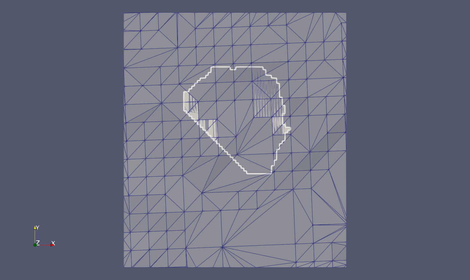
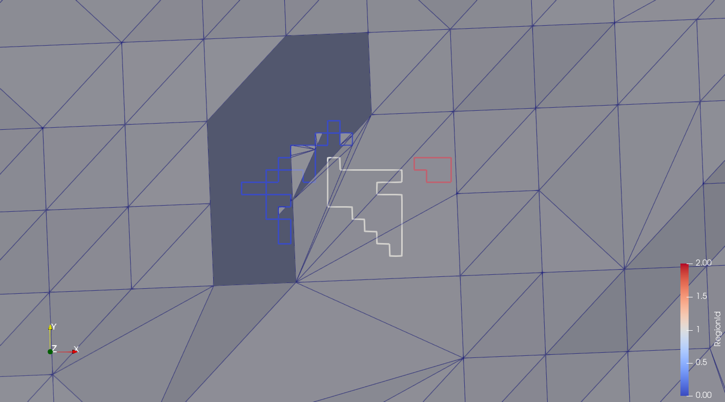
Best I deliver a test case with 3 examples, 1 working and 2 not working properly (or rather: as expected!):
- A polygon with manifold points - certainly an extra challenge! This is the first screenshot, where the blue polygon is the “loop”. Result not correct.
ring_period2_region0.vtp (19.0 KB)
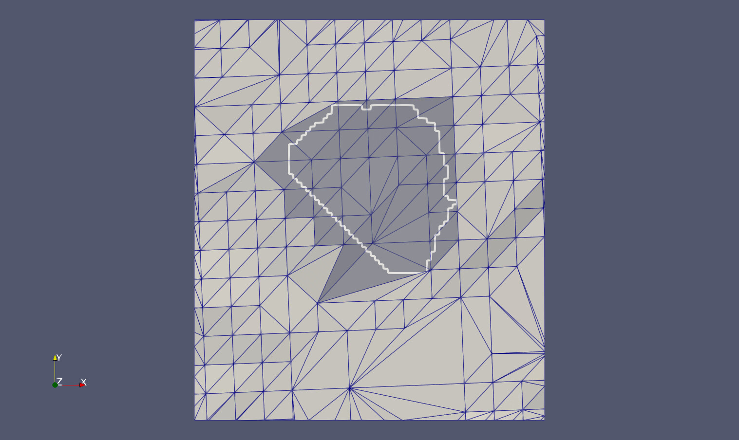
- A somewhat “complicated” polygon, working perfectly. Second screenshot, white polygon.
ring_period2_region1.vtp (19.1 KB)
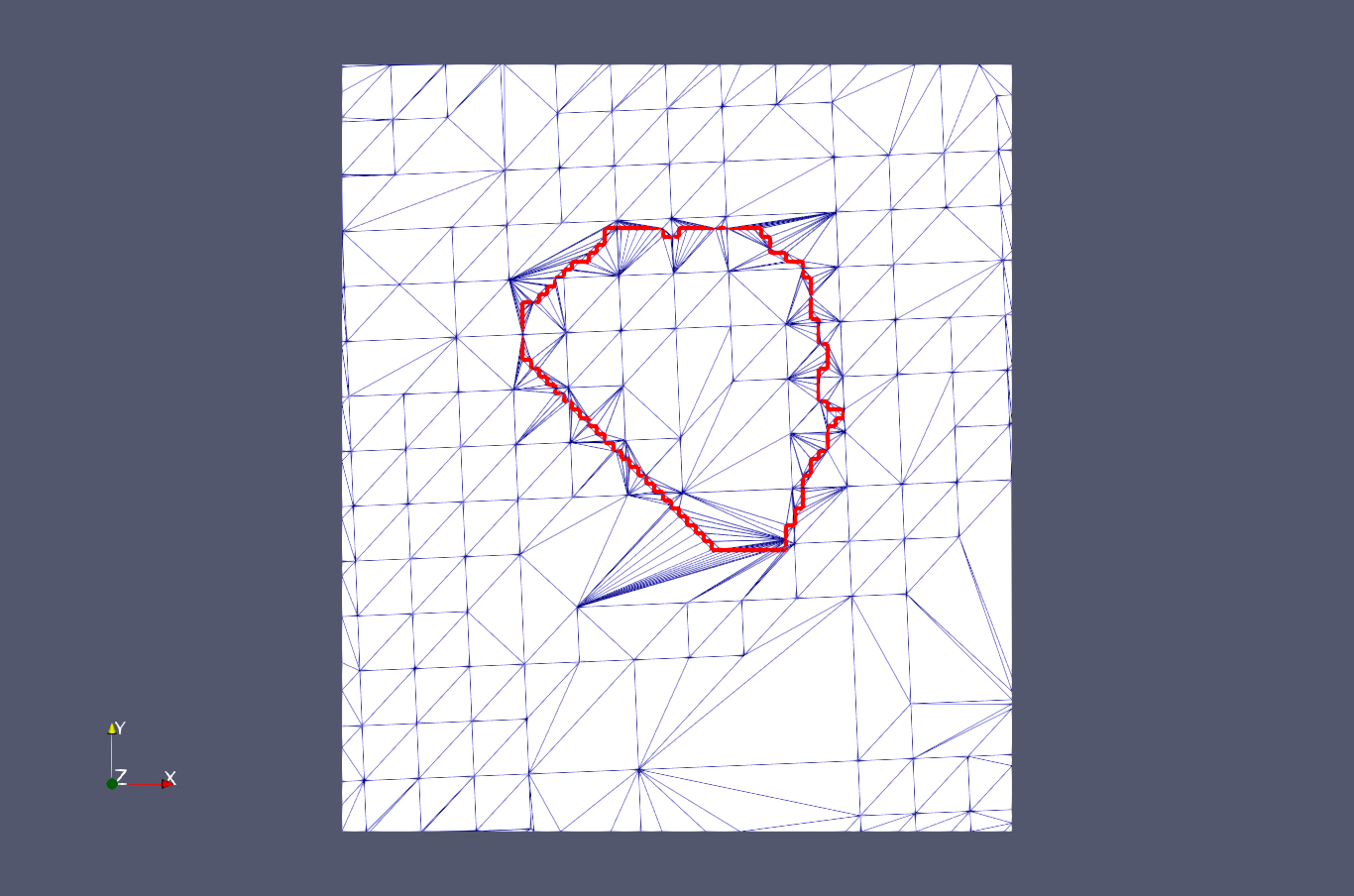
- A smaller polygon, completely falling inside a triangle of the surface triangulation. Result like described in the previous post. Third screenshot, red polygon.
ring_period2_region2.vtp (17.0 KB)
Thanks Cornelis, I very much appreciate the feedback.
The first case is likely not going to work as this is a self-intersecting polygon. But I’ll see if I can relieve this constraint - there are some in/out tests that are probably breaking.
The third case should work, I suspect that it’s a loop building issue: the inner loop is not connected to the outer loop (i.e., the triangle containing the inner loop) so I’ll have to identify this situation and build the loops appropriately.
I’ve got some deadlines this week, so it’ll be a bit until I can look at this again.
The first case is not self-intersecting in the sense that e.g. two line segments AB and CD do intersect “somewhere free in the air”: There is always also an explicit node point at the intersection, so it is rather something that you can call “manifold points”. Among my typical use cases I can exclude “real intersections” for sure, but such “manifold points” will occur regularly, so I would have to take care of them somehow if this is not handled by the imprint filter.
Meaning: I would probably have to “split” these points by duplicating them and that way explicitly tell the filter which two and two of the four line segments belong together in order to form “touching” rectangles or polygons.
The new version looks great. Thank you!
Right now, I am a little step further with my above “case 1” where the boundary line has self-intersections. Actually I replaced the vtkContourLoopExtraction filter by a similar one that takes special care of points that are shared by more than two line segments, with the following strategy:
-
Make sure that all cells are all line segments of type
VTK_LINE, i.e. two points connected by a line (like in the originalvtkContourLoopExtractionfilter). -
Apply the
vtkCleanPolyDatafilter to ensure that we have no duplicate points, because otherwise we cannot recognize potential self-intersections. -
In a loop, handle all those points that are shared by more than two cells (after calling
vtkPolyData::BuildLinks()and then using thevtkPolyData::GetPointCells(..)): First the cells are ordered by increasing “azimuth” angle, then always up to two are removed from that point by generating a duplicate of the point with same coordinates, and changing the cells in such a way that they are using the duplicates. The result is avtkPolyDataobject that has onlyVTK_LINEcells and where all points are connected with either one or two cells. -
From this input, a new
vtkPolyDataobject is generated that is made up ofVTK_POLYGONcells. First all those points with only one connected cell are handled, following the line segments until another point with no further cell is reached. (With this, they are automatically and a bit arbitrarily closed.) Second,VTK_POLYGONcells are generated by starting at a point and following the line segments until we come back to the starting point.
The result is a series of polygons that may have “self touching points” or which may touch each other, but self-intersections are excluded. The result maybe something like this, after applying a “connectivity filter” to illustrate the polygons:
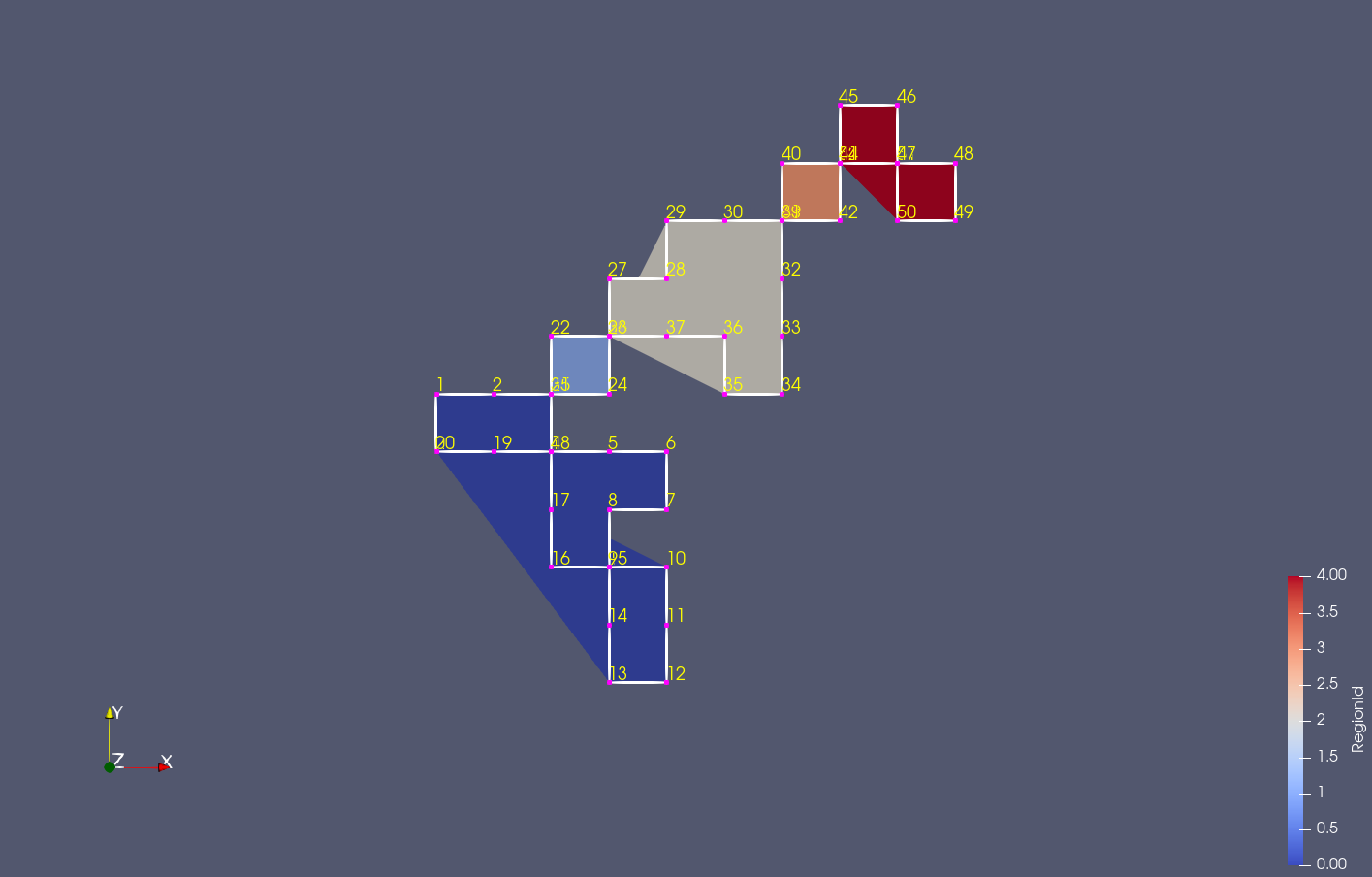
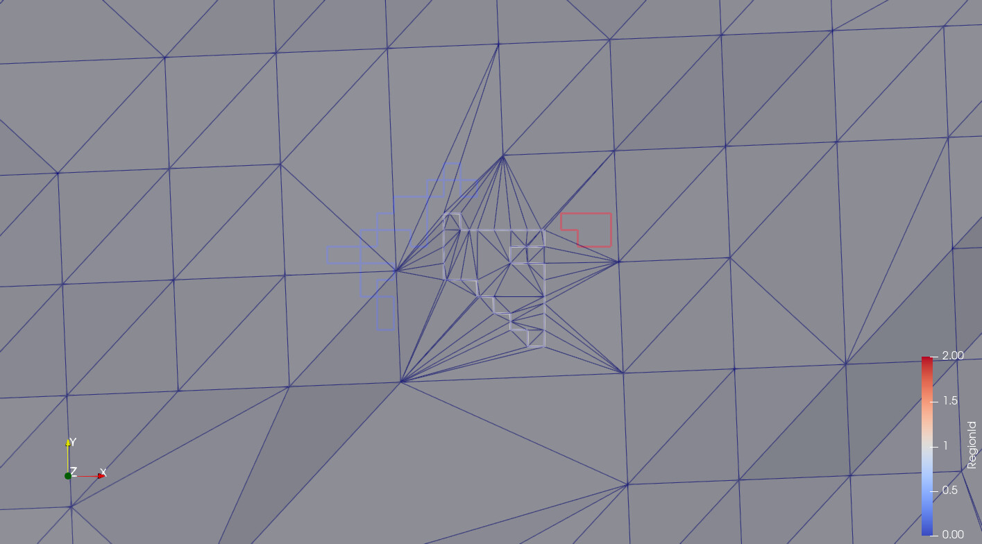
Feeding this now into your imprint filter is still not resultin in what I want, but it is still a step forward:
The new triangulation has now at least not any more edges that are crossing the boundary lines, but still they look like the algorithm was somehow “confused”. A message is generated that gives a certain hint:
vtkImprintFilterAtg.cxx:2890 WARN| vtkImprintFilterAtg (0x5626100b85a0): Merge tolerance <= 0.0
From this I conclude that it is still the fact that we have coinciding points that misleads the “imprint filter”.
I have not analyzed that filter in a way that I understand why and how it happens: Do you see a way how this can be avoided inside that filter?
One possibility that I see in my alternative “contour loop extraction filter”: Not just duplicate the points where nodes are “split”, but at the same time move them by a very small distance away, in the average direction between the two “azimuth” angles of the connected line segments.
This latter “trick” is a bit “dirty”, but in order to fine tune it a bit, I could still “remember” these “moved points” and bring them back to the original position after running the “imprint filter”.
Yes, 3D graphics is always tricky, and I also know the rule: whatever nasty case can happen will happen, so the latter “cheat” (I mean: the moving back) can in the worst case result in changed topology, degenerated triangles, changed topology in some nasty way…
All this I am just telling you in order to share my experiences, nothing specific expected from your side!
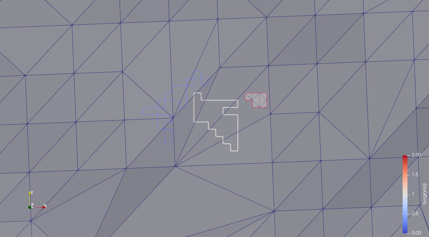
It looks like the “shifting trick” is really working:

The slightly “lighter” rectangle at the bottom is an example of the above “case 3”: That rectangle is fully located inside a triangle of the input triangulated surface, so it looks like “case 1” is at least “almost solved” now.
Note: So far, I did not realize the “back shifting” of the shifted points. (Maybe a “clean polydata” would be required afterwards!?)
Cornelis, I am still tied up with deadlines but here are a few things you can do to help:
-
imprint is designed to work with multiple “imprint” polygons. So each separate “square” can just be defined as one of many imprint polygons.
-
create simple polygons that do not touch themselves at corners.
-
send me some data
This is a variant of the first boundary after being passed through my adapted contouring filter. It is actually four non-touching (and also not self-touching) polygonsring1_shifted_points.vtp (3.4 KB)
Thanks for all your efforts, hints and tipps!