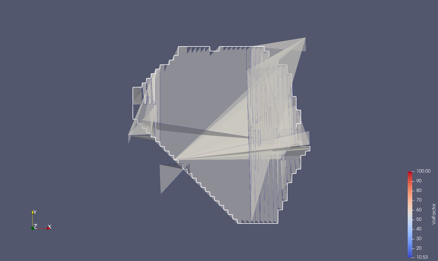
I have a triangulated surface (a “2.5D” topo surface actually), only triangles, and a closed polygon, and with that polygon I want to “punch” a hole into that triangulated topo surface. From my understanding, this should be doable with vtkClipDataset, with a specialized vtkImplicitFunction that gives me the horizontal distance from the polygon outline. The result that I am getting is below shows that it this procedure is not completely wrong, but it is far from satisfactory!
It is possible to subdivide the surface first into much smaller triangles, with the effect that the data becomes far more “heavy” and the hole will become more precise - with a lot of unnecessary extra triangulation for most of the surface -, but still far from what you would expect by “punching a polygonal hole into a surface”.
My guess is that the above strategy is probably not the right one with VTK, but are there classes or examples that come closer to exactly cutting such a hole while adapting the triangulation for the added points?
Cornelis, implicit modeling techniques generally do not give the precision necessary for geometric modeling as you discovered.
There are two classes in active development that may be able to do what you need: vtkCookieCutter and vtkImprintFilter. If you are interested in an adventure / testing these out we can help you. I’ve found them to be stable for many applications, but like any geometric algorithm requiring precise operations with finite (computer) precision, there are tolerancing issues that can bite you.
I have actually understood very well why the clipping is not so very precise in my case: It looks like the function is actually calculating the distance to that polygon line for all the points within the topo surface, and the rest is interpolating, so the resulting clipping precision depends on whether the input surface is more or less “coarse grained”. The advantage of this approach is of course, that you can clip highly complex 3D objects with equally complex other objects, as long as you can provide such a distance function.
For my specific case, “cookie cutter” sounds indeed like exactly the thing that I am looking for! So I would certainly like to give it a try. I see it already in the Paraview 5.9.1 sources on my own computer, so it is just a question of doing it.
The problems with tolerancing issues are very well known for me for many years, and I understand why it is almost impossible to solve them once and forever because of what you are writing. And the bad thing is that if some trouble is possible, it will eventually hit you, so better be prepared.
Have you considered using OpenCascade to cut your topological surface with an extruded polygon? A vtkPolyData could then be generated via their VTK integration module.
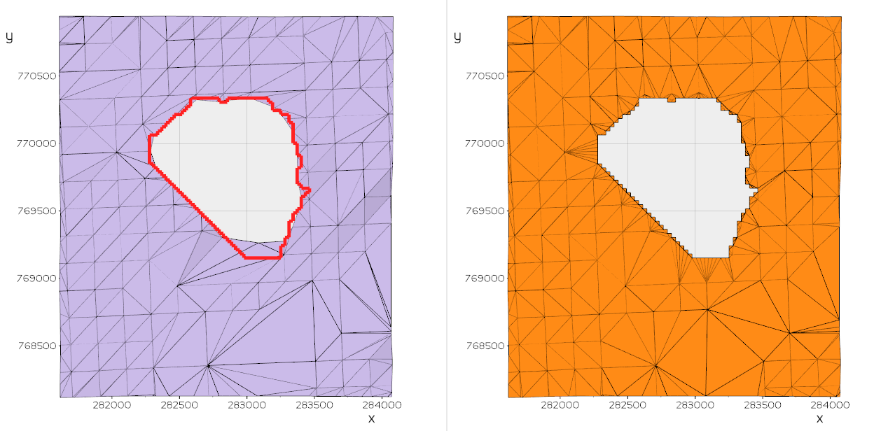
This is now done with the cookie cutter, after converting the cutter into a poly data that contains just one “cell” that is a VTK_POLYGON. Not “perfect” yet either Looks like I am still doing something wrong I guesss…
Possible, but not trivial. I tried to simplify the problem, but whatever I do, the cookie cutter does simply sensible. The most simple case I generated is a “topo” made up of two triangles, out of which I am cutting a triangle. Result: No cutting happens at all. Anyway, below I will add as much as I can in the way that you are asking.
Possible other ways further:
Is there somewhere on the net a working test case for that cookie cutter that I could use as a starting point for my code?
I am working with the vtkCookieCutter from the ParaView 5.9.1 “official release”, but this seems to be far less powerful than what I find in the most recent online documentation of ther VTK classes. Looks like it is really “work in progress”, and next thing I will try is to get the most recent code of that specific class, try if it compiles with my current 5.9.1 code here, and see what it does. The older code does not have for example the options to handle cell or point attributes.
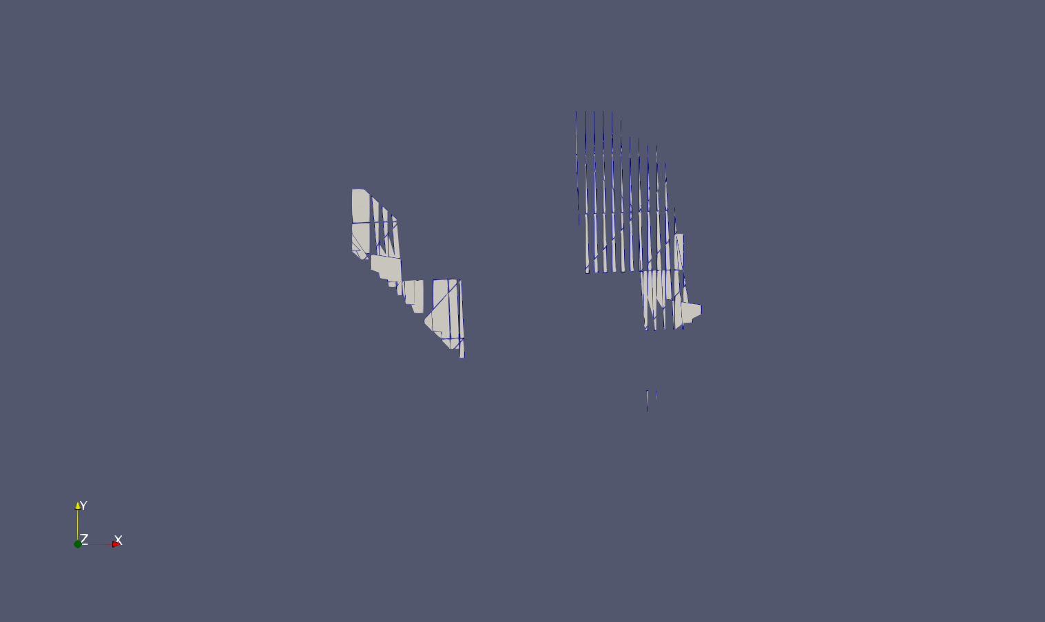
These are the boundary line and the “topo” surface that I am using
And this is the function that I wrote inside an existing filter class that does something else:(some very temporary and messy construction site for a new filter class actually). But maybe reading my code tells you already something:
vtkPolyData* vtkAtgClipGeometry::insertClipperPointsIfTopo(vtkPolyData* inPolyData, vtkPolyData* clipper)
{
    // this we are going to return: make a shallow copy in case we fail
    vtkPolyData* outSurface = vtkPolyData::New();
    outSurface->ShallowCopy(inPolyData);

    // here should now follow some code to check the conditions:
    // - inPolyData is a "topo" - see some code below
    // - clipper is a polyline or best polygon

    // a temporary shallow copy for adding another point attribute and as input for
    // the cookie cutter filter
    vtkSmartPointer<vtkPolyData> tempSurface = vtkSmartPointer<vtkPolyData>::New();
    tempSurface->DeepCopy(inPolyData);

    // add a point attribute containing the altitudes that we are going to flatten away
    vtkSmartPointer<vtkDoubleArray> alti = vtkSmartPointer<vtkDoubleArray>::New();
    alti->SetName("_TEMP_ALTITUDES_");
    vtkPoints* points = tempSurface->GetPoints();
    alti->SetNumberOfTuples(points->GetNumberOfPoints());
    for(vtkIdType p = 0; p < points->GetNumberOfPoints(); ++p)
    {
        double pt[3];
        points->GetPoint(p, pt);
        alti->SetValue(p, pt[2]);
        pt[2] = 0.;
        //points->SetPoint(p, pt);
    }
    outSurface->GetPointData()->AddArray(alti);

    // generate the loop polygons for the clipping
    vtkSmartPointer<vtkPolyData> flatClipper = vtkSmartPointer<vtkPolyData>::New();
    flatClipper->Allocate();
    vtkPoints* clipPts = clipper->GetPoints();
    flatClipper->SetPoints(clipPts);
    vtkSmartPointer<vtkIdList> clipPtIds = vtkSmartPointer<vtkIdList>::New();
    for(vtkIdType id = 0; id < clipPts->GetNumberOfPoints(); ++id)
        clipPtIds->InsertNextId(id);
    flatClipper->InsertNextCell(VTK_POLYGON, clipPtIds);

    // now let's get hold of the cookie cutter filter
    vtkSmartPointer<vtkCookieCutter> ccutter = vtkSmartPointer<vtkCookieCutter>::New();
    ccutter->SetInputData(tempSurface);
    ccutter->SetLoopsData(flatClipper);
    ccutter->Update();

    // get the new surface, as a deep copy
    outSurface->DeepCopy(ccutter->GetOutput());

    // put the altitudes back in and remove the temporary array

    return outSurface;
}
Marco: I had tried such a variant already, but I was not so happy with the fact that the retriangulation could generate artefacts in the topo surface. However, if I am programming something myself, I could extend this approach in some way, doing the same thing in two steps:
Without clipping anything, remove all triangles from the topo that are either fully inside or cut by the boundary line. Extract the inner boundary of the resulting “hole” with the feature edges extraction filter.
Triangulate only the “ring” that is delimited by the extracted feature edges and the boundary line.
Merge the two surfaces.
With this, the retriangulation would be restricted to the zone that has to be retriangulated anyway.
The data is bad. On the surface there is a small “tear” which looks to be a coincident edge. More importantly, the cookie cutting loop/polyline is not on the surface. This can be corrected with some work… the point is that these geometric modeling filters place requirements on the input data which if not met wreak havoc on the algorithm.
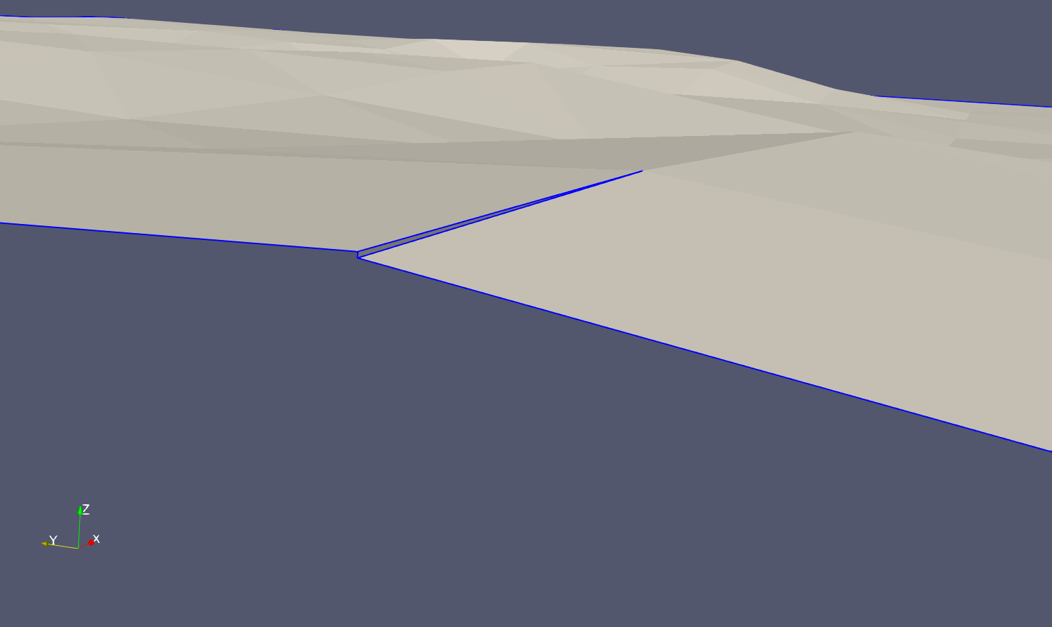
You are right: that “topo surface” is not completely correct: It has not a real “tear”, but a tiny vertical triangle - see below. In a minute I will try how removing this would affect the working of my “old” cookie cutter.
What I understood the hard way already years ago is exactly what you are saying: very small deviations from requirements can have very bad effects of functionality of geometric algorithms. But I also learned that there are two “environments” that require different handling of these cases:
In the context of VTK, I see that algorithms are implemented as efficient as possible, also for large data sets. Little inconsistencies (meaning: hardly visible by eye) in the data sets have to be strictly avoided because it is assumed that they do not exist; doing otherwise, like checking everywhere, would require a high price in terms of performance and generate a lot of redundancy. For these reasons, the current way how VTK handles these things is for me absolutely correct. (Only little criticism: Sometimes I would be happy to have requirements more explicitly documented, but whether this is a need or not depends a lot on how much the programmers are familiar with certain modelling terminology and logic.)
The customers for whom I am working do not have any mathematical or modelling background. They receive “topo surfaces” from some surveyor, very often with far too much redundancy, and full of little flaws. So what I always have to do is: Make sure that I can fix these flaws as much as possible, and only in the very worst cases give an error message to the users, but these have to be very very clear because, as I said already, these people will NOT understand in most cases! Instead they will simply dump the software entirely, saying that “it does not work”.
For this reason, I know that I have to take care of two things:
a) Whenever possible, go for robust algorithms that do not care so much about little geometric flaws.
b) If some algorighm seems to be the most suitable, I have to understand as much as possible the preconditions and make sure that I can fix them silently, so the user thinks that everything is just fine. But this can be really tricky! Like dealing with the case that e.g. a “cutter” would cut exactly through a mesh point, or exactly along the edge of a triangle, etc. etc. - I do not have to explain I think.
Bottom line: From your remark I conclude that maybe the “cookie cutter” is not or still not the tool for my case, but maybe the one that also Todd calls the probably only efficient way to get it done. Still already the example of Marco shows that also this seems to be a bit tricky in detail, because his “quick and dirty” first attempt is obviously also not what I need!
And here the little flaw that I could detect in the “topo surface”:
The real problem is the cutting loop is positioned well off of the surface. It’s not the fold (although cookie cutter assumes that everything is homeomorphic to a plane) and it performs line-line intersections so the trim loop cannot cut the edges.
To deal with possibly bad data the integration process (built into the application) must deal with potential issues, or do validation on the input. For example, the cookie trim loop and mesh have to be projected onto a plane.
vtkDelaunay, with folded over edges as you show, and due to its own inherent numerical sensitivity may fail at some point.
Right, that was another thing. In a first version of my code I did that “flattening” explicitly, making first a copy of the input surface and cutter and replace the vtkPoints by a variant where all z are explicitly set to 0.
But then I was asking myself: If that plugin assumes that all points are at the same level, this sounds like it simply does not care about the third coordinate? But in this case I would have to do this entire procedure - so I tried this. And after the “totally wrong” result, I did not any more try to put the extra code back in…
Now reading again in the documentation, I see that I cannot even blame that one! Actually it says: Warning:The mesh and trim loops must lie on the same plane and the plane may be arbitrarily oriented. If not on the same plane, tolerancing issues can produce erratic results.
So the “assuming” came somehow in my brain, but not from the documentation, and generated some confusion there…
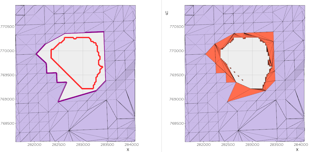
This is now another attempt, with the cookie cutter from PV 5.9.1 “release”, with both surface and cutter previously flattened at level 0 - still not much more convincing:
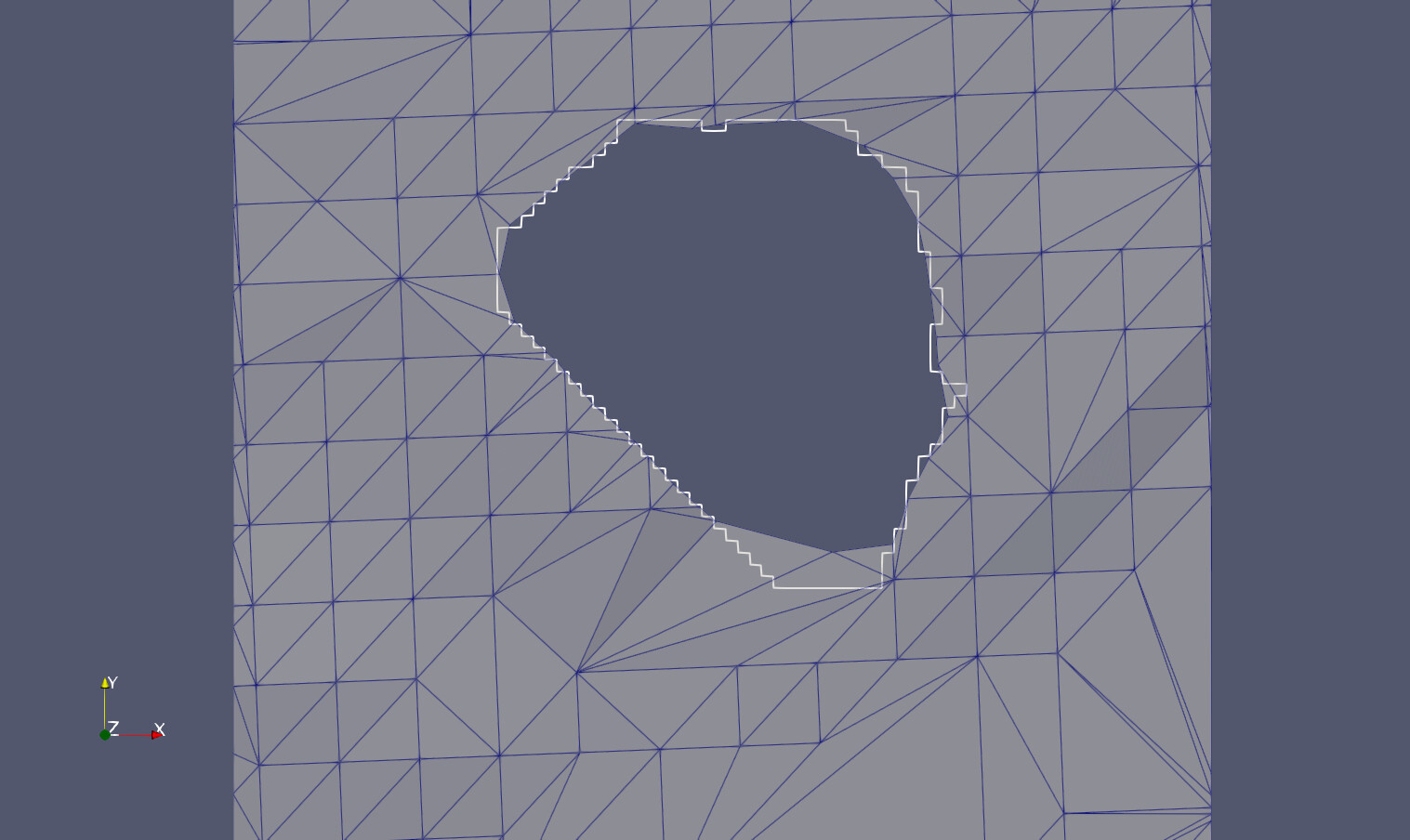
 Looks like I am still doing something wrong I guesss…