Slice from vtkImagereslice has additional black edges

Hi eveyone,
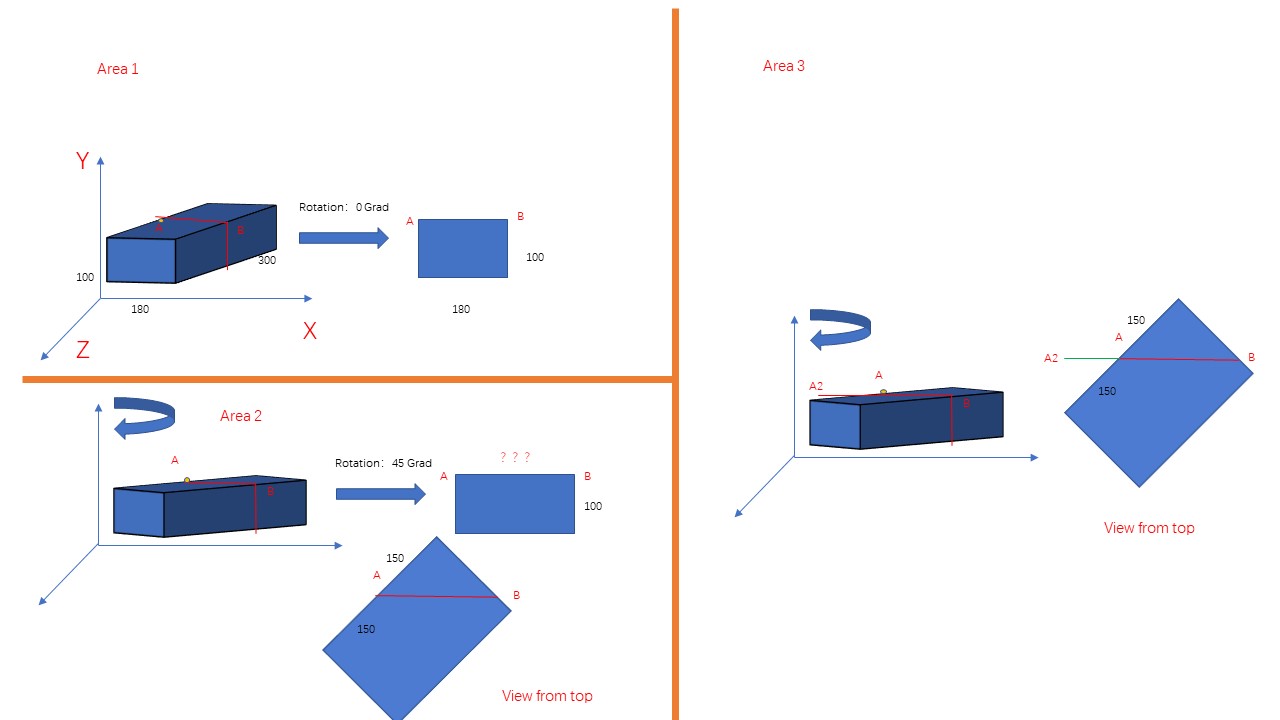
I have a 3D-volume ,its size is as following:
witdth:180mm,X
height:100mm,Y
depth:300 mm,Z
it likes a fallen cuboid.
At begining camera faces to xy-plane which means 180*100 mm.
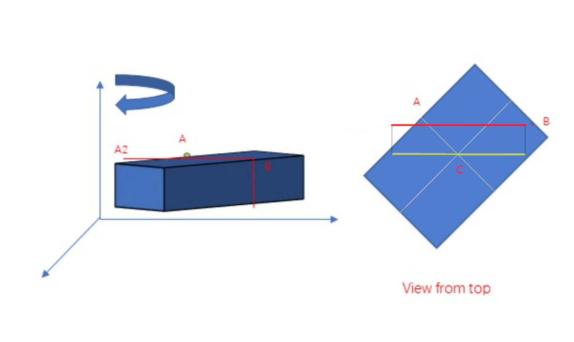
Now I want to extract a slice from any direction.
So I utilize vtkimagereslice filter and vtkMatrix4x4 as rotation matrix, The rotation is around the Y-axis, i.e., along a 100 mm edge. FinallyI use imageviewer2 to display the result .
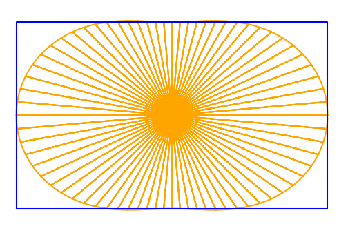
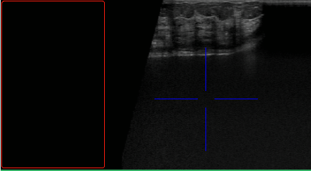
Code compile successfully and the reslice looks right. But it has annoying additional black edges at left side(the origin point on middle of top left edge). In other words, the FOV is bigger than it should be. It seems like that vtkimagereslice automatic create this area and fill it all zero.

Here is the screenshot ,the parts that are framed in red are the black areas that shouldnā€™t be there.
WeChat Screenshot_20201001150026

Here is my code in minisize:

void cut(double angle) {
vtkImageData* reslice;
vtkNew<vtkImageReslice> imageReslice;
vtkNew<vtkMatrix4x4> resliceAxes;
vtkNew<vtkImageViewer2> image_view_reslice;

double axialElements[16] = {
cos(angle), 0, sin(angle), 0,
0		  , 1,		0,	   0,
-sin(angle),0, cos(angle), 0,
0,			0,	    0,	   1 };
this->resliceAxes->DeepCopy(axialElements);
//std::cout << "origin :" << center[0] << "," << center[1] << "," << center[2] << endl;

resliceAxes->SetElement(0, 3, source_center[0] - Xmmus / 2 + 16);
resliceAxes->SetElement(1, 3, source_center[1] + Ymmus / 2 - 1);
resliceAxes->SetElement(2, 3, source_center[2]);

imageReslice->SetOutputDimensionality(2);
imageReslice->SetResliceAxes(this->resliceAxes);
imageReslice->SetInterpolationModeToCubic();
//this->imageReslice->AutoCropOutputOn();
imageReslice->Update();


int extent[6];
imageReslice->GetOutput()->GetExtent(extent);
double origin[3];
this->imageReslice->GetOutput()->GetOrigin(origin);
double spacing[3];
imageReslice->GetOutput()->GetSpacing(spacing);
float xc = origin[0] + 0.5*(extent[0] + extent[1])*spacing[0];
float yc = origin[1] + 0.5*(extent[2] + extent[3])*spacing[1];
float zc = origin[2] + 0.5*(extent[4] + extent[5])*spacing[2];

float xd = (extent[1] - extent[0] + 1)*spacing[0]; 
float yd = (extent[3] - extent[2] + 1)*spacing[1];
float zd = (extent[5] - extent[4] + 1)*spacing[2];

image_view_reslice->SetInputConnection(imageReslice->GetOutputPort());
image_view_reslice->GetRenderer()->GetActiveCamera()->ParallelProjectionOn();
image_view_reslice->GetRenderer()->GetActiveCamera()->SetParallelScale(0.5f*static_cast<float>(yd));
float d = image_view_reslice->GetRenderer()->GetActiveCamera()->GetDistance();
image_view_reslice->GetRenderer()->GetActiveCamera()->SetFocalPoint(xc, yc, 0);
image_view_reslice->GetRenderer()->GetActiveCamera()->SetPosition(xc, yc, +d);
image_view_reslice->UpdateDisplayExtent();
image_view_reslice->Render();
ui->usImagereslice->update();
ui->usImagereslice->show();

Itā€™s best to specify the output cropping yourself (with reslice->SetOutputExtent(), reslice->SetOutputOrigin()) rather than relying on vtkImageReslice to set the cropping for you.

It looks like there is a math error in this code here:

resliceAxes->SetElement(0, 3, source_center[0] - Xmmus / 2 + 16);
resliceAxes->SetElement(1, 3, source_center[1] + Ymmus / 2 - 1);
resliceAxes->SetElement(2, 3, source_center[2]);

Are Xmmus and Ymmus are the size of the 2D output slice that you want to generate? And (-Xmmus/2 + 16, +Ymmus/2 - 1, 0) is a displacement you want to apply? If so, then before you put this displacement into the ResliceAxes, you must multiply it by your rotation matrix.

The 4th column of the ResliceAxes is a translation vector that works like this:

T_input + R*T_output

where T_output is a translation to apply in resliceā€™s output coords and T_input is a translation to apply in resliceā€™s input coords. You have done something that looks like this:

 T_input + T_output

But that will not work, because output coords do not have the same orientation as input coords!

1 Like

Thanks for your reply! I should make that code part about rotation matrix easier to understand. Source_center is the center point of 3d volume,it is in world coords. And Xmmus and Ymmus are not the output size, they are the original size of 3D volume along X and Y direction . Iā€™m sorry I didnā€™t explain those variables. I did that strange math in code because I want to make sure my reslice always through the point which at mid of top-left edge(actually the point is near by top left edge ) That point is fixed,all slice I created should pass through it. In other words, my rotation is around that point. So I think my rotation matrix is correct.

I drew 3 diagrams to show the work I wanted to do. The cube in the diagram is representing the dataļ¼Œ
A is that fixed point.which i set in colum 4 in my rotation matrix .
AB is the long side of output slice and rotation around Y axis.


If rotation angle is 0 then I will got reslice A that should be 180 x 100mm (area 1)
If rotation angle is 45 then I will got reslice B that should be AB x 100mm(area 2)
I used to think the AB line was 150*āˆš2,Actually, The results would be bigger.
I think its real size is like in area 3 I show . real AB= AB+AA2
AA2 is 150\āˆš2
Am I right?

Iā€™ve made a diagram that shows how vtkImageReslice does the cropping with its default settings. The cropping is based on the center of the rotated volume, and on the dimensions of the volume:

If you rotate by 45 degrees, then vtkImageReslice will set the crop width (the length of the red line) to (100 + 150)/2, which is 125. There is no āˆš2 in this answer.

For other rotations, the crop width will be (100*cos(angle)**2 + 150*sin(angle)**2). So for angle=0, it will be 100, and for angle=90, it will be 150.

Why the equation of crop width isā€™(100cos(angle)**2 + 150sin(angle)**2)ā€™?
I think in equation should not do square. And the volume original width is 180 , height is 100. For crop width,100 , the original height should play no role. so may be you write it wrong.
And from your diagram the red line is equal to yellow line and should be 180*āœ“2.
Imagine that, if you rotate 90 degrees, which means show the side view of original volume. The crop width should be 300 not 150.

Sorry, I made a mistake with the numbers. That makes my last post almost useless, unfortunately : ( You are correct, it should be 180 and 300, instead of 100 and 150.

As for the equation, it should not do a square, but it does. When vtkImageReslice computes the default cropping, it squares the direction cosines. So as far as I understand the code in vtkImageReslice, it will compute the length of the red and yellow lines to be 240 (using 180 and 300 as the dimensions and a 45 degree angle).

Note that I didnā€™t draw the lines in the diagram to scale, my primary purpose was to show how the cropping is based on the center of the volume, and how this results in the extra black area that you reported in your initial post.

1 Like

Thanks a lot! I understand your purpose. But the default crop will do a square, that is a really strange computation. As you said the cropping is based on the center of volume. So the crop width will not exceed the diagonal length of ā€œview from topā€ , right? I canā€™t check that in my code now because I left my computer adapter in office. I know some of my mistakes after our discussion.As long as I verify the black area problem, I will perfect this answer, thank you again!

For dimensions of 300 and 180, here is a figure that shows the crop width (yellow line) the vtkImageReslice will apply when ResliceAxes is used to apply a rotation:
cropwidth

For certain angles, the crop will be slightly larger than the corresponding diagonal line across the rectangle. I think this was your question? For a square (e.g. 180 x 180), the crop will be the same for all angles.

Please note that this cropping is applied by default because the vtkImageReslice TransformInputSampling flag is On. You can use reslice->TransformInputSamplingOff() and then the cropping will be the same as it was in the original, unrotated image.

When I use vtkImageReslice in my own code, I always ignore the TransformInputSampling and AutoCropOutput flags. Instead, I use SetOutputOrigin(), SetOutputExtent(), and SetOutputSpacing() to manually set the cropping and sample spacing to whatever values I need for the problem I am trying to solve. I really donā€™t think there is any ā€œone size fits allā€ solution, it always depends on the requirements of the application.

1 Like

This diagram is very clear, and I can imagine that if it were a square, the yellow line inside would be a circleļ¼Œthen : the crop will be the same for all angles.

But I have my doubts about that sentence. I saw none of the yellow lines in the diagram are longer than the diagonal.

What I mean is, in some places (top and bottom) the yellow lines go slightly beyond the rectangle.

I got it! Thank you again!
If I wanted to get a diagonal slice, I would have to manually set SetOutputOrigin() , SetOutputExtent() , and SetOutputSpacing() .Otherwise using the default cropping method the result will smaller than real diagonal slice should be,right?

Yes, exactly.

Then I thought, the formula for the yellow line should be
reslice width =original_width*cos(angle)**2 + original_height*sin(angle)**2
if width is equal to height then the formula will be simplified to reslice width = original_width
due to cos(angle)**2+sin(angle)**2=1.
Thank you very much! I think I should have figured out in Class vtkImagereslice how cropping works.