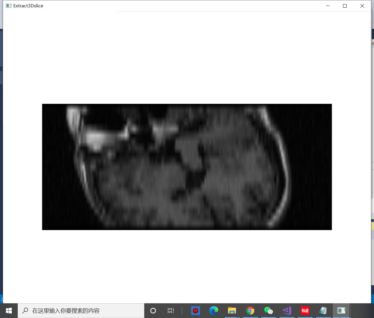
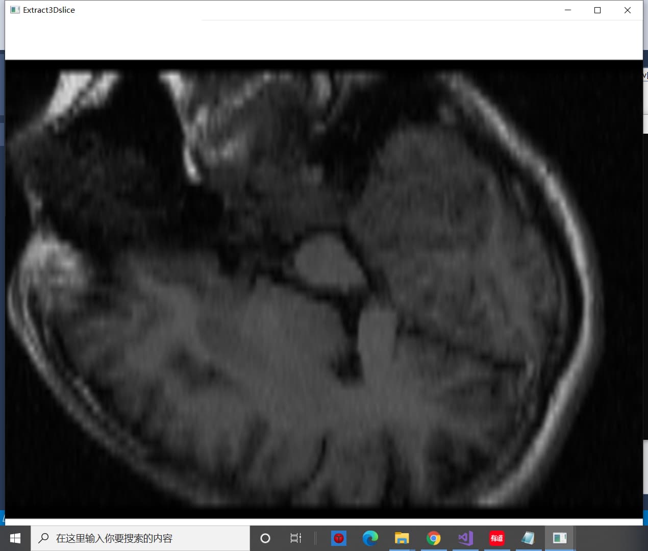
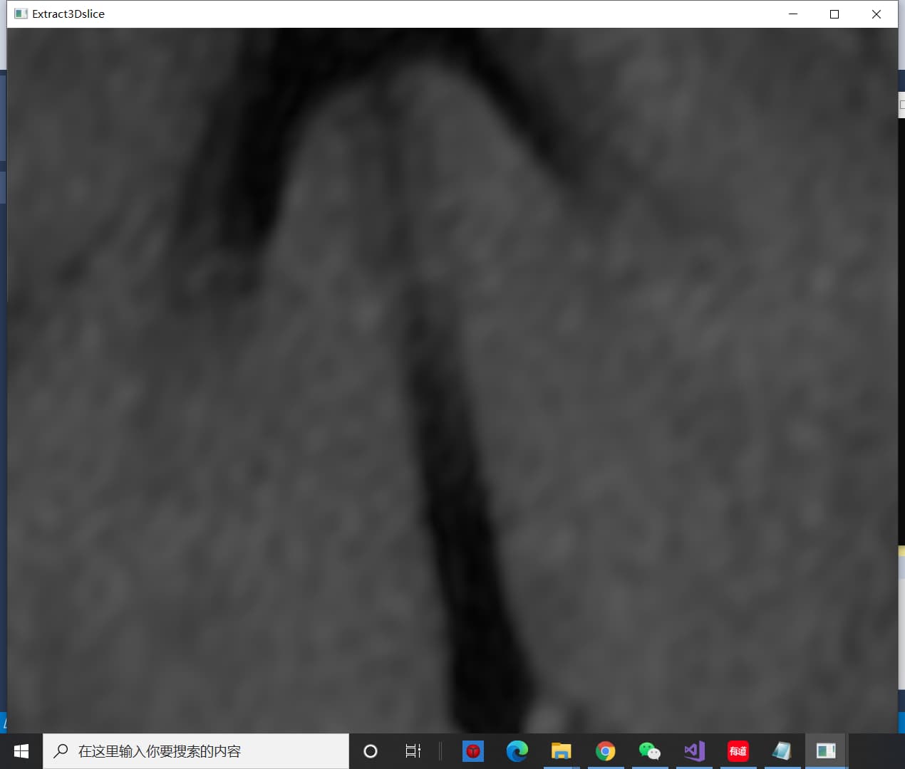
My question is: How do I get a fixed size image?
I use a sensor to control the Angle and make VTK image continuously. But the picture gets bigger and smaller. The problem is the same for both 512×512×24-format 3d data and 194×204×190-format 3D data. These are some of the images I produced when I used 512×512×24-format file.
Here is my code:
#include "vtkAutoInit.h"
VTK_MODULE_INIT(vtkRenderingOpenGL2);
VTK_MODULE_INIT(vtkInteractionStyle);

#include <vtkSmartPointer.h>
#include <vtkImageData.h>
#include <vtkMetaImageReader.h>
#include <vtkMatrix4x4.h> //
#include <vtkImageReslice.h>
#include <vtkLookupTable.h>
#include <vtkImageMapToColors.h>
#include <vtkImageActor.h>
#include <vtkRenderer.h>
#include <vtkRenderWindow.h>
#include <vtkRenderWindowInteractor.h>
#include <vtkInteractorStyleImage.h>
#include <Python.h>

int main(int argc, char* argv[])
{

	//---------------------------------------------------
	//调用python程序
		//Py_SetPythonHome(L"C:\\Program Files (x86)\\Microsoft Visual Studio\\Shared\\Python36_64");
		/**
		这句语句是在添加python.exe所在路径,不添加虽然编译没有问题,但是会在运行时出现
		Fatal Python error: initfsencoding: unable to load the file system codec
		ModuleNotFoundError: No module named 'encodings'
		这种错误
		**/
	Py_Initialize();//使用python之前,要调用Py_Initialize();这个函数进行初始化
	if (!Py_IsInitialized())
	{
		printf("初始化失败!");
		return 0;
	}
	else
	{
		PyRun_SimpleString("import sys");
		PyRun_SimpleString("sys.path.append('./')");//这一步很重要,修改Python路径

		PyObject * pModule = NULL;//声明变量

		PyObject * pFunc1 = NULL;// 声明变量
		PyObject * pFunc2 = NULL;
		PyObject * pFunc3 = NULL;

		PyObject * pValue = NULL;

		pModule = PyImport_ImportModule("WitSensor");//这里是要调用的文件名WitSensor.py
		if (pModule == NULL)
		{
			//如果显示‘没找到该python文件’而没找出问题,有可能是因为此python中的接口设置不对(com3)
			cout << "没找到该python文件" << endl;
		}
		else
		{

			//pFunc1 = PyObject_GetAttrString(pModule, "get_angle");//这里是要调用的函数名
			//pFunc2 = PyObject_GetAttrString(pModule, "DueData");
			pFunc3 = PyObject_GetAttrString(pModule, "mainfunc");

			pValue = PyObject_CallObject(pFunc3, NULL);//调用函数

			float x, y, z;
			PyArg_ParseTuple(pValue, "f|f|f", &x, &y, &z);


			//**************
			vtkSmartPointer<vtkMetaImageReader> reader =
				vtkSmartPointer<vtkMetaImageReader>::New();
			//vtkImageReader2是vtkMetaImageReader的父类,SetFileName是从vtkImageReader2中继承的
			//mhd用来存放信息,raw用来存放数据?
			reader->SetFileName("E:\\MyVTKwork\\resource_w\\brain\\brain.mhd");
			//vtkAlgorithm←vtkImageAlgorithm←vtkImageReader2←vtkMetaImageReader(继承关系)
			reader->Update();

			int extent[6];//设置XYZ的范围
			double spacing[3];//设置立方体单元格间距
			double origin[3];

			//在每个轴上,范围extent由第一个点的索引和最后一个点的索引定义。extent按XYZ的顺序存储
			//(是不是说extent[0]是x轴范围的起始坐标,extent[1]是x轴范围的结束坐标?后面依次类推?)
			//GetOutput():获取此算法上端口的输出数据对象;GetExtent(int [6]):获取数据集的范围
			reader->GetOutput()->GetExtent(extent);
			//GetSpacing(double [3]):获取组成数据集的立方体单元格的间距(宽度、高度、长度)。
			reader->GetOutput()->GetSpacing(spacing);
			//GetOrigin(double [3]):获取原点位置(起始点)
			reader->GetOutput()->GetOrigin(origin);

			//center应该就是中心点,center[0]、center[1]、center[2]应该就是XYZ轴中心点的坐标
			double center[3];
			//(extent[0]+extent[1])*0.5是x轴范围的中点,再*此轴上的间距spacing[0]就是实际的x轴中点
			//yz轴同理
			center[0] = origin[0] + spacing[0] * 0.5 * (extent[0] + extent[1]);
			center[1] = origin[1] + spacing[1] * 0.5 * (extent[2] + extent[3]);
			center[2] = origin[2] + spacing[2] * 0.5 * (extent[4] + extent[5]);
			//*****************************************************************//

			////斜切面
			//static double axialElements[16] = {
			//	1, 0, 0, 0,
			//	0, 0.866025, -0.5, 0,
			//	0, 0.5, 0.866025, 0,
			//	0, 0, 0, 1
			//};

			////平行于XY平面
			//static double axialElements[16] = {
			//	1, 0, 0, 0,
			//	0, 1, 0, 0,
			//	0, 0, 1, 0,
			//	0, 0, 0, 1
			//};

			////平行于XZ平面
			//static double axialElements[16] = {
			//	1, 0, 0, 0,
			//	0, 0, 1, 0,
			//	0, -1, 0, 0,
			//	0, 0, 0, 1
			//};

			////平行于YZ平面
			//static double axialElements[16] = {
			//	0, 0,-1, 0,
			//	1, 0, 0, 0,
			//	0,-1, 0, 0,
			//	0, 0, 0, 1
			//};


			//angle为角度,radian为弧度,C++中cos函数中对应的为弧度值
			float x_angle, y_angle, z_angle, x_radian, y_radian, z_radian;
			/*cin >> x_angle >> y_angle >> z_angle;*/
			x_angle = x;
			y_angle = y;
			z_angle = z;

			float pi = 3.1415926;
			x_radian = pi * x_angle / 180;
			y_radian = pi * y_angle / 180;
			z_radian = pi * z_angle / 180;
			//测试平面
			//具有一般性的切面
			const double axialElements[16] = {
			   cos(y_radian),cos(x_radian)*cos(z_radian),cos(x_radian),0,
			   -cos(x_radian),cos(y_radian)*cos(z_radian),cos(y_radian),0,
			   0,-pow(cos(x_radian),2) - pow(cos(y_radian),2),cos(z_radian),0,
			   0,0,0,1
			};
			//平行于XY平面的切面
			const double axialElements2[16] = {
				   1, 0, 0, 0,
				   0, 1, 0, 0,
				   0, 0, 1, 0,
				   0, 0, 0, 1
			};

			/*static double axialElements[16] = {
			   cos(y_radian),cos(x_radian)*cos(z_radian),cos(x_radian),0,
			   -cos(x_radian),cos(y_radian)*cos(z_radian),cos(y_radian),0,
			   0,-pow(cos(x_radian),2) - pow(cos(y_radian),2),cos(z_radian),0,
			   0,0,0,1
			   };*/

			   /*
			   关于这个矩阵的一些说明:
			   首先,最后 1 列是原点坐标;
			   最后 1 行必须是 0 0 0 1;
			   第 123 列要相互正交,且遵循右手定则;
			   第 3 列为切面的法向量;
			   第 1 列和第 2 列是沿切片平面边缘的单位向量(将切片平面想象为矩形);
			   */

			vtkSmartPointer<vtkMatrix4x4> resliceAxes =
				vtkSmartPointer<vtkMatrix4x4>::New();
			//判断是否方向向量的角度是否垂直于XY平面,从而避免正交向量出现0向量
			if (x_angle == 90 && y_angle == 90 && z_angle == 0)
			{
				resliceAxes->DeepCopy(axialElements2);
			}
			else
			{
				resliceAxes->DeepCopy(axialElements);
			}

			/*
			vtkMartrix4x4结构:
			00 01 02 03   03被赋值为center[0]
			10 11 12 13   13被赋值为center[1]
			20 21 22 23   23被赋值为center[2]
			30 31 32 33
			综上所述,最后一列为中心点坐标
			(参考资料说矩阵前三列分别表示x、y、z方向向量?)
			*/
			resliceAxes->SetElement(0, 3, center[0]);
			resliceAxes->SetElement(1, 3, center[1]);
			resliceAxes->SetElement(2, 3, center[2]);

			//vtkImageReslice这个类的作用:沿着一组新的坐标轴重新切割一个物体
			vtkSmartPointer<vtkImageReslice> reslice =
				vtkSmartPointer<vtkImageReslice>::New();
			//SetInputConnection:为给定的输入端口索引设置连接
			reslice->SetInputConnection(reader->GetOutputPort());
			//SetOutputDimensionality:强制输出的维度为1、2、3或0(默认为3),此例中是2
			reslice->SetOutputDimensionality(2);
			//SetResliceAxes:设置输出体素的坐标轴
			/*
			矩阵的第一列指定x轴向量(第四个元素必须设置为0),第二列指定y轴,第三列指定z轴;
			第四列是坐标轴的原点(第四个元素必须设置为1)
			(以上是官方说明,可以说第四行元素要设置为0 0 0 1)
			*/
			reslice->SetResliceAxes(resliceAxes);
			//SetInterpolationModeToLinear()指定了切面提取中的差值方式为线性差值;此外还有其他插值
			reslice->SetInterpolationModeToLinear();

			//*****************************************************************//
			//vtkLookupTable:通过查找表把标量值映射为颜色
			vtkSmartPointer<vtkLookupTable> colorTable =
				vtkSmartPointer<vtkLookupTable>::New();
			colorTable->SetRange(0, 1000);	//设置要映射的标量范围
			colorTable->SetValueRange(0.0, 1.0);	//设置值中的范围,取值范围[0,1]
			colorTable->SetSaturationRange(0.0, 0.0);	//设置饱和度范围
			colorTable->SetRampToLinear();	//将表格坡道的形状设置为线性
			colorTable->Build();	//从色调,饱和度,值,alpha最小/最大值生成查找表

			//vtkImageMapToColors:通过查找表映射输入图像
			vtkSmartPointer<vtkImageMapToColors> colorMap =
				vtkSmartPointer<vtkImageMapToColors>::New();
			colorMap->SetLookupTable(colorTable);	//设置查找表
			colorMap->SetInputConnection(reslice->GetOutputPort());	//为给定的输入端口索引设置连接
			colorMap->Update();
			//*****************************************************************//
			//vtkImageActor:在渲染的3D场景中绘制图像
			vtkSmartPointer<vtkImageActor> imgActor =
				vtkSmartPointer<vtkImageActor>::New();
			imgActor->SetInputData(colorMap->GetOutput());	//设置图像数据输入

			vtkSmartPointer<vtkRenderer> renderer =
				vtkSmartPointer<vtkRenderer>::New();	//渲染器
			renderer->AddActor(imgActor);	//向渲染器中添加不同类型的道具(这里是vtkImageActor类型的)
			renderer->SetBackground(1.0, 1.0, 1.0);	//使用rgb颜色规范,设置渲染屏幕的背景颜色

			//vtkRenderWindow:为渲染器创建一个绘图窗口
			vtkSmartPointer<vtkRenderWindow> renderWindow =
				vtkSmartPointer<vtkRenderWindow>::New();
			renderWindow->AddRenderer(renderer);	//将渲染器添加到渲染器列表中
			renderWindow->Render();	//要求这个RenderWindow拥有的每个渲染器渲染它的图像并同步这个过程
			renderWindow->SetSize(1000, 1000);	//以屏幕坐标(像素为单位)设置渲染窗口的大小(宽度和高度)
			renderWindow->SetWindowName("Extract3Dslice");	//渲染窗口的名称


			while (1)
			{


				pValue = PyObject_CallObject(pFunc3, NULL);//调用函数
				PyArg_ParseTuple(pValue, "f|f|f", &x, &y, &z);


				x_radian = pi * x / 180;
				y_radian = pi * y / 180;
				z_radian = pi * z / 180;

				const double axialElements[16] = {
				   cos(y_radian),cos(x_radian)*cos(z_radian),cos(x_radian),0,
				   -cos(x_radian),cos(y_radian)*cos(z_radian),cos(y_radian),0,
				   0,-pow(cos(x_radian),2) - pow(cos(y_radian),2),cos(z_radian),0,
				   0,0,0,1
				};


				if (x_angle == 90 && y_angle == 90 && z_angle == 0)
				{
					resliceAxes->DeepCopy(axialElements2);
				}
				else
				{
					resliceAxes->DeepCopy(axialElements);
				}


				resliceAxes->SetElement(0, 3, center[0]);
				resliceAxes->SetElement(1, 3, center[1]);
				resliceAxes->SetElement(2, 3, center[2]);


				reslice->SetResliceAxes(resliceAxes);
				reslice->Update();


				colorMap->SetInputConnection(reslice->GetOutputPort());	//为给定的输入端口索引设置连接
				colorMap->Update();


				imgActor->SetInputData(colorMap->GetOutput());	//设置图像数据输入


				//vtkSmartPointer<vtkRenderer> renderer =
				//	vtkSmartPointer<vtkRenderer>::New();	//渲染器
				renderer->AddActor(imgActor);	//向渲染器中添加不同类型的道具(这里是vtkImageActor类型的)
				//renderer->SetBackground(1.0, 1.0, 1.0);	//使用rgb颜色规范,设置渲染屏幕的背景颜色


				renderWindow->AddRenderer(renderer);	//将渲染器添加到渲染器列表中
				renderWindow->Render();	//要求这个RenderWindow拥有的每个渲染器渲染它的图像并同步这个过程

				//renderer->Delete();

			}
			reader->Delete();
			resliceAxes->Delete();
			reslice->Delete();
			colorTable->Delete();
			colorMap->Delete();
			imgActor->Delete();
			renderer->Delete();
			renderWindow->Delete();


		}
		Py_Finalize();//调用Py_Finalize,这个和Py_Initialize相对应的。
	}

	system("pause");

	//---------------------------------------------------
	return 0;
}
The Python file is what I use to read the sensor Angle.
This is my first time using VTK community and my English needs improving.
Finally, thank you for your help.
supplement:
If I create vtkSmartPointer renderer repeatedly in while(1), the image will display more normally. But it only lasted a few seconds, because I didn’t destroy it. But renderWindow always needs a renderer to use.