I am using vtkClipPolyData to cut a mesh, but it give a incorrect result.
The code is:
import vtkmodules.all as vtk
import numpy as np

def CreateActor(ply: vtk.vtkPolyData, color=[1, 0, 0]):

    mapper = vtk.vtkPolyDataMapper()
    mapper.SetInputData(ply)
    mapper.ScalarVisibilityOff()

    actor = vtk.vtkActor()
    actor.SetMapper(mapper)

    actor.GetProperty().SetColor(color[0], color[1], color[2])
    actor.GetProperty().SetOpacity(0.3)
    return actor

def CutMesh(ply: vtk.vtkPolyData):
    plyClone = vtk.vtkPolyData()
    plyClone.DeepCopy(ply)

    centers = np.array([
        [25.54791, 131.9023, 570.03764],
        [46.95663, 83.99182, 511.02341],
        [58.50379, 42.54272, 577.24325],
        [37.09508, 90.45326, 636.25748],
    ])

    ############################################################################
    ########## after remove the minus sign, this function output a wrong cut result
    normals = -np.array([  # NOTE THE MINUS SIGN
        [0.34503, -0.93555, 0.07544],
        [-0.07840, 0.05137, 0.99560],
        [-0.34503, 0.93555, -0.07544],
        [0.07840, -0.05137, -0.99560],
    ])
    ############################################################################

    vpoints = vtk.vtkPoints()
    for i in range(4):
        vpoints.InsertNextPoint(centers[i])
    vectors = vtk.vtkFloatArray()
    vectors.SetNumberOfComponents(3)
    for n in normals:
        vectors.InsertNextTuple3(n[0], n[1], n[2])

    planes = vtk.vtkPlanes()
    planes.SetPoints(vpoints)
    planes.SetNormals(vectors)

    clipper = vtk.vtkClipPolyData()
    clipper.SetInputData(plyClone)
    clipper.SetClipFunction(planes)
    clipper.GenerateClippedOutputOff()
    clipper.GenerateClipScalarsOff()
    clipper.SetValue(0)
    clipper.Update()

    newply = clipper.GetOutput()
    return CreateActor(newply, [0, 1, 0])

reader = vtk.vtkOBJReader()
reader.SetFileName('before.obj')
reader.Update()

oriMesh = CreateActor(reader.GetOutput(), [1, 0, 0])
newMesh = CutMesh(reader.GetOutput())

renderer = vtk.vtkRenderer()
renderer.AddActor(oriMesh)
renderer.AddActor(newMesh)
renderer.SetBackground(1, 1, 1)


renWin = vtk.vtkRenderWindow()
renWin.AddRenderer(renderer)
iren = vtk.vtkRenderWindowInteractor()
iren.SetRenderWindow(renWin)
iren.SetInteractorStyle(vtk.vtkInteractorStyleTrackballCamera())
iren.Initialize()
iren.Start()
The data is: https://github.com/zhang-qiang-github/data/blob/main/before.obj
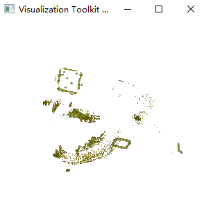
The result is correct:
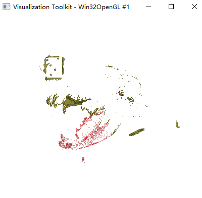
Fig. 1
The whole mesh is the original mesh. The yellow mesh is the cutted result.
However, if I remove the minu sign for normals, for example:
    ############################################################################
    ########## after remove the minus sign, this function output a wrong cutted result
    normals = np.array([  # NOTE THE MINUS SIGN
        [0.34503, -0.93555, 0.07544],
        [-0.07840, 0.05137, 0.99560],
        [-0.34503, 0.93555, -0.07544],
        [0.07840, -0.05137, -0.99560],
    ])
    ############################################################################
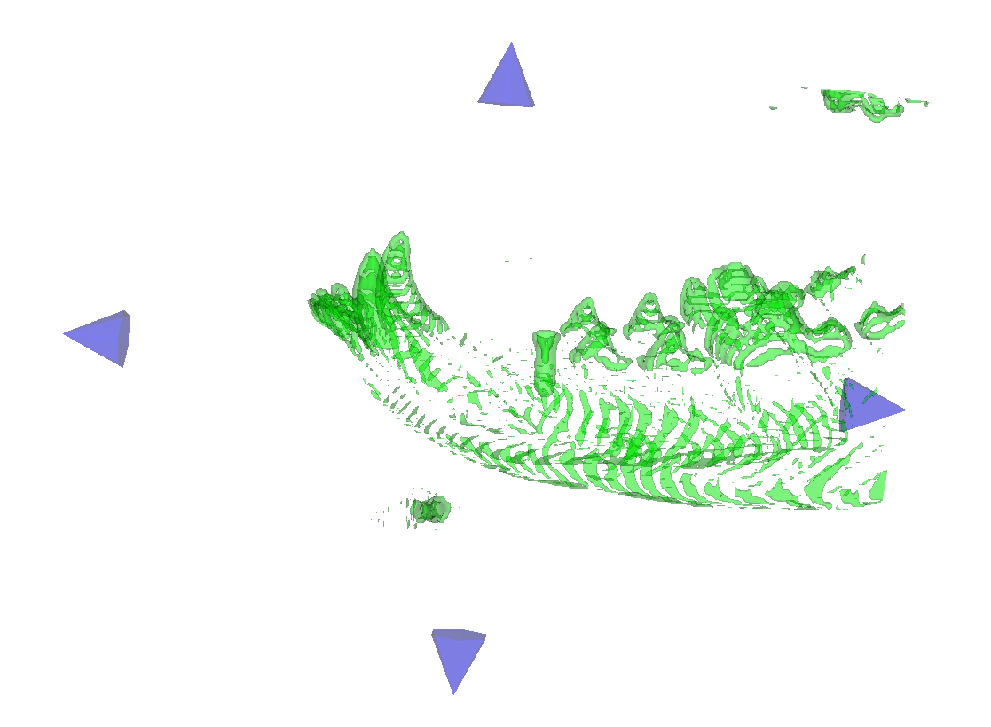
In my opinion, the cutted part should be the red part in Fig. 1. However, the result is:
The environment is:
win 10
python 3.9.12
vtk 9.2.6
Any suggestion is appreciated~~~