Since my previous question went unanswered (vtkTubeFilter - representation and intersections) I looked around a little bit and it seems to me that vtkHyperStreamLine could be used to create a “tube” representation having an elliptical cross-section.
Basically I have a curve in 3D defined by a certain number of points, and at each point I know the length of the two axes of the ellipse. I’ve looked at the vtkHyperStreamLine and there’s a lot of talk about eigenvectors, but does anyone know of a more straightforward way to construct a streamline given the information I have?
Maybe my math is very poor, any suggestions would be more than welcome.
Hey Andrea,
maybe it’s not a question about your maths but about your understanding of Hyperstreamlines.
Let me lay it out for you quickly:
The input for hyperstreamlines is a 3D tensor field. From the 3D tensors you can compute the three eigenvectors and three eigenvalues, namely major, middle (or intermediate), and minor. This means that you end up with three fields for the eigenvectors and three fields for the eigenvalues.
The way hyperstreamlines are computed is then the following:
Use the major eigenvector field to integrate the a streamline representing for example the “flow” of stress in a material.
Use the middle and minor eigenvalues to scale the axes of the ellipsoids forming the tube around the streamline.
If we now try to translate that concept to the data that you have, we end up with essentially two options:
You can hijack the VTK code to take three arrays as input. A vector field for the streamline integration, and the two fields defining your axis lengths.
You can generate a tensor field representing your data and use the VTK filter as is.
Thank you for your suggestions. I’ll see what I can do with both of them. Paulo’s suggestion appears to be easier to implement, although I first have to understand how to create one ellipse at each point of the 3D curve, having this ellipse somehow “perpendicular” to the segment I’m analyzing. I know that “perpendicular “ makes no sense in this context but I can’t come up with the proper term here…
It should kind of look like vtkTubeFilter but with an ellipse as cross-section.
I have tried to follow your recommendation, and it kind of works but not as well as I thought. I will put a little script that can be used to look at my problem, but this is the description of the issue I am having:
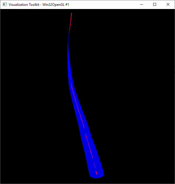
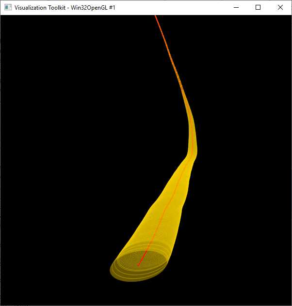
The script appears to make an elliptic tube around the 3D curve, but actually you can see through the tube and see the curve inside - which is not supposed to happen, what kind of tube is it? See the attached picture “tube_01.png” as an example
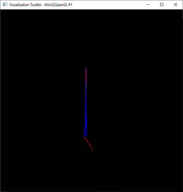
If you rotate the camera around so that the horizontal part of the curve is perpendicular to the observer, you will see that the tube completely disappears. See the attached picture “tube_02.png” as an example
I am definitely doing something wrong and I’d appreciate any suggestion you may have. I have been using Windows 10 64 bit, VTK 7.1.0, Python 2.7.3 and numpy 1.11.2 . I know Python 2.7 is out of date but I am doing this work on a quite old legacy application.
For SetExtrusionTypeToNormalExtrusion() to work properly, you need to set normal vectors for each vertex. The normal vector tells VTK how to orient the extrusion result (among other things such as shading). You can set normals like this:
normals = vtkFloatArray()
normals.SetNumberOfComponents(3)  #3 = normals are x,y,z
normals.SetNumberOfTuples(4) #4 = if the number of vertexes 4

for i in range(4) :
   normals.SetTuple3( i , 0., 0. , 1. ) #all normals will point towards Z axis

polydata = vtkPolyData()

(...)

pointData = polydata.GetPointData()
pointData.SetNormals(normals)
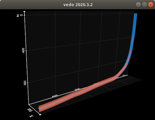
if point uncertainties in your measurements refer to the cartesian coordinates (or one axis is small wrt the other two), then you might consider using vtkRibbonFilter or vtkRuledSurfaceFilter instead of an extruded ellipse, e.g. in vedo (works in python2 and 3):
I have modified the make_ellipse method to incorporate your suggestions but now nothing gets rendered on screen. I only get a black render window with no 3D curve nor elliptic tube.
I had also tried other extrusion types in my code (which are currently commented out) - such as SetExtrusionTypeToVectorExtrusion and SetExtrusionTypeToPointExtrusion but all gave the same pictures I sent before…
Don’t give up the first time you get unexpected results. VTK never yields easily. I suggest reducing your problem to a trivial working case: add a single line with two vertexes, check result; add an ellipse centered on one of the two vertexes, check result; extrude the ellipse down the line, check result. Develop on it in baby steps. Don’t try to solve everything in a single shot. With VTK you have to tread carefully.
I have reduced the sample to just look at the last two points of the curve, and made the ellipse bigger so it is plain to see that it is not extruded down the line. It’s plain obvious by running the attached script and rotating a bit the view around. It seems that the ellipse stays in the x-y plane and it is extruded along some unknown direction.
Since the documentation on the extrusion types is zero, my understanding is that this piece of code:
is supposed to extrude something along that vector. So if I have 2 points A and B, and I want to extrude something along AB (from A to B), my vector should supposedly be something like:
your approach has of course a lot of potential, and I like very much what you have done with vtkplotter first and vedo now. Especially your reworking and re-interpretation of the broken vtkAxis and vtkCubeAxesActor is phenomenal.
I might end up following your suggestion if the other route becomes impassable, although for the moment I’ve taken it as a personal snub and insult from VTK and I’d like to understand at least why the ellipse approach does not work. And also because elliptic tubes would look much more appropriate for my application.
Ah well, if I have to rotate the ellipse in 3D then I’m back to what I was saying in one of my first replies:
Then of course it’s obvious, I got sidetracked by Paulo’s comment:
“ Extrusion works by… er… extruding… a shape along a path. It’s supposed to be simple.”
Maybe I’ve misunderstood the original intent and now that I think about it it’s obvious that you have to tell VTK how to rotate the ellipse. So I’m back to my original idea and I’ll just have to figure out how to put the ellipse in space before extruding it.
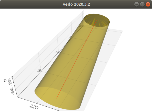
I made the tube half transparent so I could see the inside too. Now the only thing I need is a way to smooth out the resulting polydata so that it becomes a nice, smooth surface without all those visible lines. I am not sure if it is possible bu I welcome any suggestion on this matter as well .
Thanks to Paulo an Marco for your suggestions, and to anyone who would like to chip in and help me close this issue.
I’m already doing that. If you look at the attachment I sent yesterday you’ll see that I am appending each extrusion to a vtkAppendPolyData and then using vtkCleanPolyData on the result. It doesn’t seem to do much overall…
Thank you Marco, it’s almost perfect now. I’ll have to live with some very minor visual artifacts happening when the curve has sharper turns - as the ellipse changed its inclination more abruptly - but nothing major, I’m happy .
 a shape along a path. It’s supposed to be simple. A “seed” ellipse can be generated either programmactially with sines and cosines in a loop or by chaining