vtkImageReslice with vtkBoxWidget

Hi,

I am trying to reslice a vtkImageData with an interactive vtkBoxWidget. Once the box is placed correctly, I pass the vtkTransform obtained from the box widget to vtkImageReslice.
My tests are with VTK 9.2.6 from conda-forge.

To test that I am doing things correctly I started with simply cropping a test image on the 3 axes. My test image contains a sphere (bottom left), a cylinder (top left) and a parallepiped (top right).
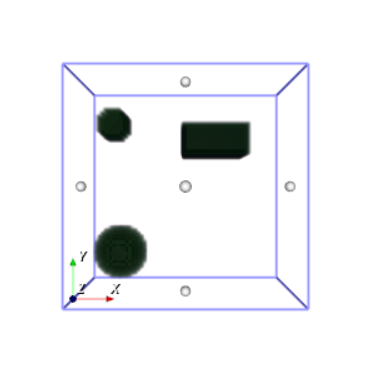
image

I try to crop the image above around the sphere. The box I configure is not a cube, but a parallelepiped, see below. My expectation is that the output will be a cropped image, i.e. the dimensions will be less in all axes.
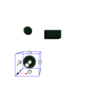
image

The code below produces a visual output that I expect however, it maintains the original input extent and dimensions while changing the spacing. What I would want is to maintain the spacing and reduce the extent (dimensions), i.e. I would like to crop.


trans = vtk.vtkTransform()
box_widget.GetTransform(trans)
    
reslice = vtk.vtkImageReslice()
reslice.SetInterpolationModeToCubic()
reslice.SetResliceTransform(trans)
reslice.SetInputData(img)
reslice.TransformInputSamplingOn()
reslice.Update()

I have tried to change the output origin and extent of vtkImageReslice, but never got it to work as intended. To know how many voxels I should have in the output, I currently calculate the distance between parallel planes of the box.


reslice.SetOutputExtent(*extent)
reslice.SetOutputOrigin(*origs)

The important bits of my code are here CIL-work/viewer/minimal_box_widget_example.py at 8572d1a2b4a0c324df73db48e765ab429f228aba · paskino/CIL-work · GitHub

Any help is welcome.

Cheers

Edo

You would need to send the inverse transform to vtkImageReslice, since it takes a transform that goes from output coords -> input coords.

Even then, I don’t think you will get the result that you want. I’ve never used vtkBoxWidget, but the docs say that its transform is the transform that takes the original box, from PlaceWidget(*bbox), to the user-adjusted box. So if you apply the inverse of that transform to the image with vtkImageReslice, then vtkImageReslice is going to stretch out the part of the image in your crop box so that it fills the widget’s original bbox.

My feeling is that vtkBoxWidget and vtkImageReslice just don’t fit together very well.

Thanks @dgobbi for your comments.

I believe I managed to use the ingredients to obtain what I want, though further tests are required. Basically the steps are:

  1. determine the extent of the output image from the box size using the distance between parallel planes. From this I establish the number of voxels necessary in the output vtkImageData
  2. Give vtkImageReslice the reslice axes origin, by transforming the origin of the original image with the box widget transform
  3. Give vtkImageReslice the ResliceAxesDirectionCosines obtained from the box planes
  4. Use the spacing of the input image

origin = trans.TransformPoint(img.GetOrigin())
reslice.SetResliceAxesOrigin(*origin)

plane_dir_cos = [planes.GetPlane(1).GetNormal(), planes.GetPlane(3).GetNormal(), planes.GetPlane(5).GetNormal()]
reslice.SetResliceAxesDirectionCosines(*plane_dir_cos)

extent = [int(el) for i,el in enumerate([0, tshape[0] , 0, tshape[1] , 0, tshape[2]])]
reslice.SetOutputExtent(*extent)

reslice.SetOutputOrigin(0,0,0)
orig_spacing = img.GetSpacing()
reslice.SetOutputSpacing(*orig_spacing)

reslice.AutoCropOutputOn()

To determine tshape, i.e. point 1 I use the following code:


    planes = vtk.vtkPlanes()
    box_widget.GetPlanes(planes)
    vmath = vtk.vtkMath()
    vec = vtk.vtkVector3d()           
    # planes 0 and 1 are parallel and originally placed with normal parallel to x axis
    # planes 2 and 3 are parallel and originally placed with normal parallel to y axis
    # planes 4 and 5 are parallel and originally placed with normal parallel to z axis
    tshape = [0, 0, 0]
    origs = [0,0,0]
    normal_vectors = [[1,0,0], [0,1,0], [0,0,1]]
    for i in range(planes.GetNumberOfPlanes()):
        for j in range(planes.GetNumberOfPlanes()):
            if i != j:
                # find if planes are parallel by checking if the normals are parallel
                vmath.Cross(planes.GetPlane(i).GetNormal(), planes.GetPlane(j).GetNormal(), vec)
                if vmath.Norm(vec) < 1e-5:
                    # here we should be only with (0, 1), (2, 3), (4, 5) pairs
                    orig = planes.GetPlane(j).GetOrigin()
                    dist = planes.GetPlane(i).DistanceToPlane(orig)
                    # this loop gets both (0, 1) and (1, 0) pairs
                    alpha = vmath.AngleBetweenVectors(planes.GetPlane(i//2).GetNormal(), normal_vectors[i//2])
                    tshape[i//2] = dist * img.GetSpacing()[i//2] / m.cos( alpha / 360 * 2 * m.pi)

I think that point 4 should be revisited, because I’m thinking now that the spacing should change with the different orientation of the box. Both spacing and number of pixels should be determined by the box size and orientation in space with respect to the input image.