Hi I am using ActiViz.Net 64 v5.8.0
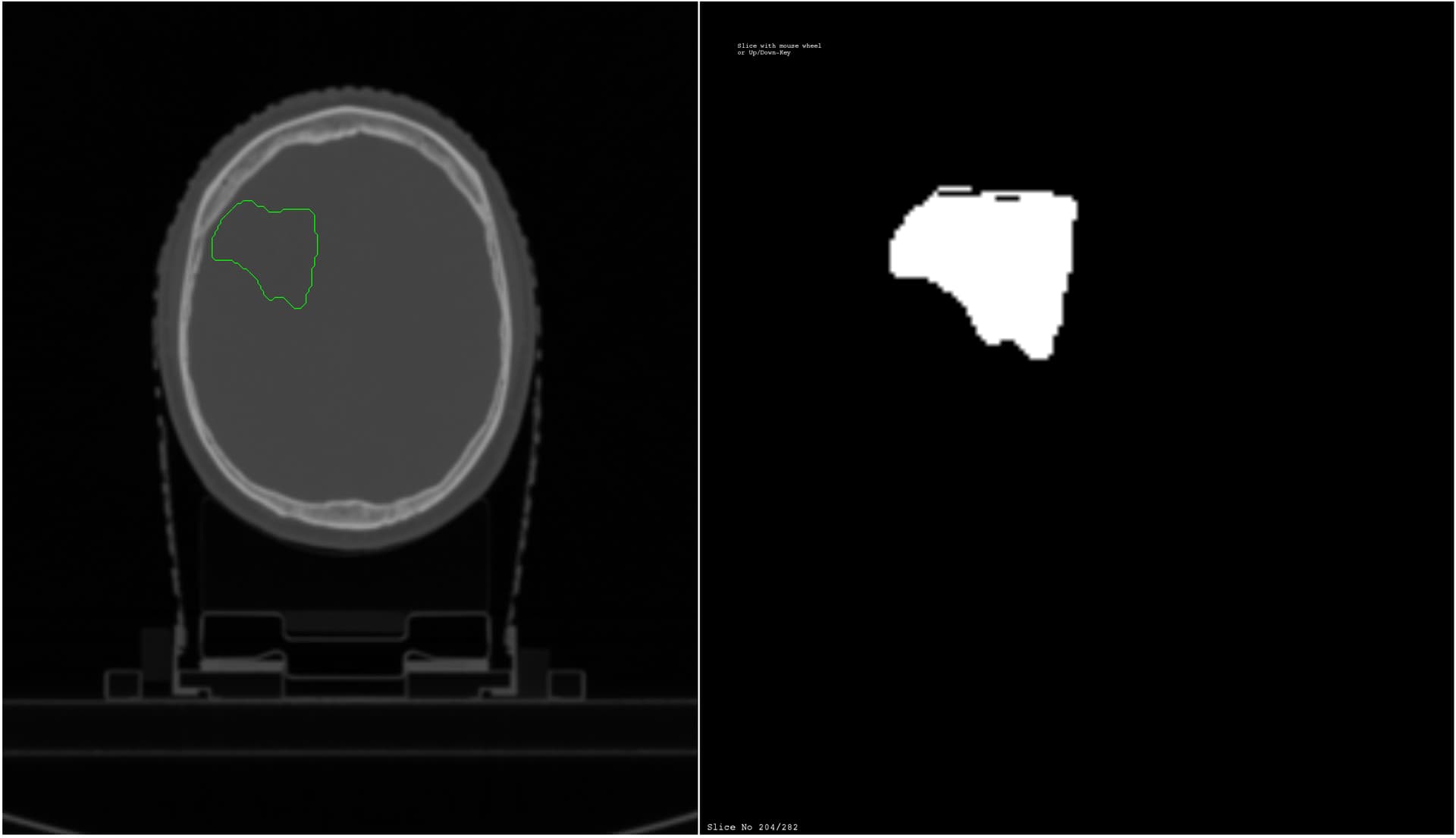
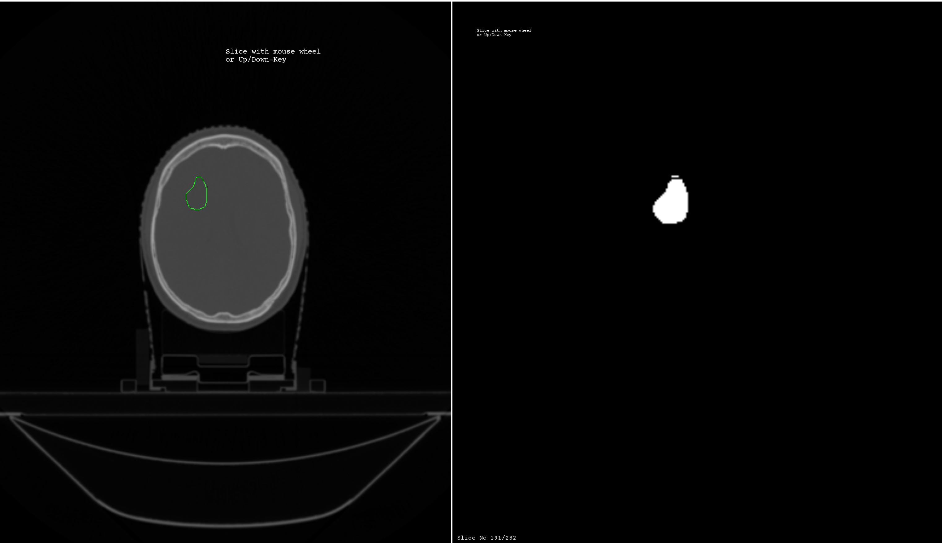
I am having an issue with vtkPolyDataToImageStencil where the output seems to have either extra lines or holes. I have attempted to combine vtkPolyDataToImageStencil with vtkImageStencilToImage as well as vtkImageStencil the resulting imageData is the same
I have tried to change the vtkPolyDataToImageStencil .SetTolerance parameter but that makes it even worse not matter the value .
I have tried running my vtkPolyData ( points and lines) through vtkCleanPolyData that had no effect i could tell .
I am convinced that my my contour (vtkPolyData) is correct since it displays fine as a contour overlay.
Any suggestions or help would be greatly appreciated
You need to merge the points and order the line segments (for example using vtkCleanPolyData followed by vtkStripper) before you can use them in vtkPolyDataToImageStencil.
However, if you want to be able to convert arbitrary parallel contour sets to 3D labelmap then you need to solve several non-trivial problems (branching, holes, end-capping, etc.). If you are converting contrours coming from DICOM RT structure sets then it is even worse, as holes are defined using keyhole technique (instead of polygon winding direction, as it is usual in computer graphics). The most robust and full-featured planar contour set to 3D labelmap converter implementation that I know of is in SlicerRT, which takes care of all the mentioned issues. SlicerRT is based on VTK and can be used from Python scripting or via 3D Slicer GUI.
It is true that the contour points are coming DICOM RT , However what I am failing to understand ( and please correct me if I am wrong) that the contour set ( the vtkPolyData with the points and lines ) displays correctly as an overlay , points are correct, there are no holes and the contours show on the correct slice. I have also tried using a trace widget drawn weird shapes on the screen and vtkPolyDataToImageStencil does the stencelling correct no issues .
I mean what is so different from the points drawn with the tracewidget vs points coming from DICOM RT ? Shouldn’t the vtkPolyDataToImageStencil handle all the points in the same fashion ?
Also I have tried using vtkCleanPolyData as input to the vtkPolyDataToImageStencil it made 0 difference that I could tell.
I am aware that Slicer RT does open and display the DICOM RT struct contours and such , but we are doing something specific. I just need to stay in one platform and need a way to create a binary mask from the contour points
 vtkCleanPolyData cPolyData = new vtkCleanPolyData();
 cPolyData.SetInput(t5_PolyDataContours);
 cPolyData.ConvertLinesToPointsOn();
 cPolyData.ConvertPolysToLinesOn();
 cPolyData.ConvertStripsToPolysOn();
 cPolyData.SetTolerance(0.0001);
 cPolyData.Update();

t5_dataToStencil.SetInput(cPolyData.GetOutput());
/// and so on with the pipeline
There can be many different representations that are rendered visually exactly the same way. For example, for rendering it does not matter that the line segments are ordered randomly.
You need to use vtkStripper as well.
You can use 3D Slicer simply from the command line, run it as a docker container, expose it as a web service, etc., so it should be accessible in your platform, no matter what operating system and software environment you are working in.
I will try to add vtkStripper to my pipeline before the vtkCleanPolyData and see what happens
I have another question if you do not mind , I originally tried the exact same pipeline with the exact same contours in 2D, essentially I was loading and splitting the DICOMs into single frames and I did not see any issues at all creating the masks in 2D , all of this started with the contour vtkPolyData being 3D, so my question is what happens when all of the sudden there are multiple contours on different z planes ?
When you mentioned the ordering of the line segments , doesn’t the following assign the points and lines in order ?
vtkPolyData pdLeft = new vtkPolyData();
vtkPoints pointsLeft = new vtkPoints();
vtkCellArray linesLeft = new vtkCellArray();
int totalpoints = 0;
 foreach (ContourImageSequence x in ListOfCountour)
            {
                List<CoorPoint> coords = x.getContourData().getValue();
                      for (int i = 0; i < coords.Count; i++)
                             {
                                      c = coords[i];
                                     pointsLeft.InsertPoint(i + totalpoints, (c.x), (c.y), (c.z));
                             }
              for (int i = 0; i < coords.Count - 1; i++)
                {
                    vtkLine newLine = new vtkLine();
                    newLine.GetPointIds().SetId(0, i + totalpoints);
                    newLine.GetPointIds().SetId(1, i + totalpoints + 1);
                    linesLeft.InsertNextCell(newLine);
                    if (i + 1 == coords.Count - 1)
                    {
                        newLine = new vtkLine();
                        newLine.GetPointIds().SetId(0, i + 1 + totalpoints);
                        newLine.GetPointIds().SetId(1, totalpoints);
                        linesLeft.InsertNextCell(newLine);
                    }
                }
            pdLeft.SetPoints(pointsLeft);
            pdLeft.SetLines(linesLeft);
            pdLeft.Update();
            }
You are starting to see why it is hard to rasterize DICOM RTSTRUCT. This is the problem that I referred to by “branching”. Although the DICOM standard would allow specification of references between contours, in practice you just have to guess what contours are continuation of another contour from the previous slice. Of course, the contours can branch out, holes can appear, etc. so you need to develop very smart algorithms that make the correct guesses.
The conversion algorithms in SlicerRT were developed for several years and tested on thousands of data sets, but every now and then we still receive data sets that are messed up in some unexpected ways. SlicerRT’s converter is also different from most of the naive implementations in that it interpolates between the slices but it keeps the original contours unchanged (so a round-trip loading of contours, visualization, and saving does not alter the data).
Overall, I would recommend to spend time with interfacing with SlicerRT rather than reimplementing a converter from scratch.
Using vtkStripper made no difference.
I think I am gone give it a shot at creating the mask in 2D from individual contours and use vtkImageAppend to append slices of vtkImageData to recreate the 3D binary mask volume.
Unless you can suggest another filter that would combine 2D vtkImageData
Either way thank you very much Andras