I set up an off screen rendering pipeline using the vtkSmartVolumeMapper to render a vtkImageData. In the first case I set two scalars so have the color and opacity LUT independent. For the vtkVolumeProperty I turned the IndependentComponents to off and it renders as I would expect. And the color and opacity are independent as I expect.
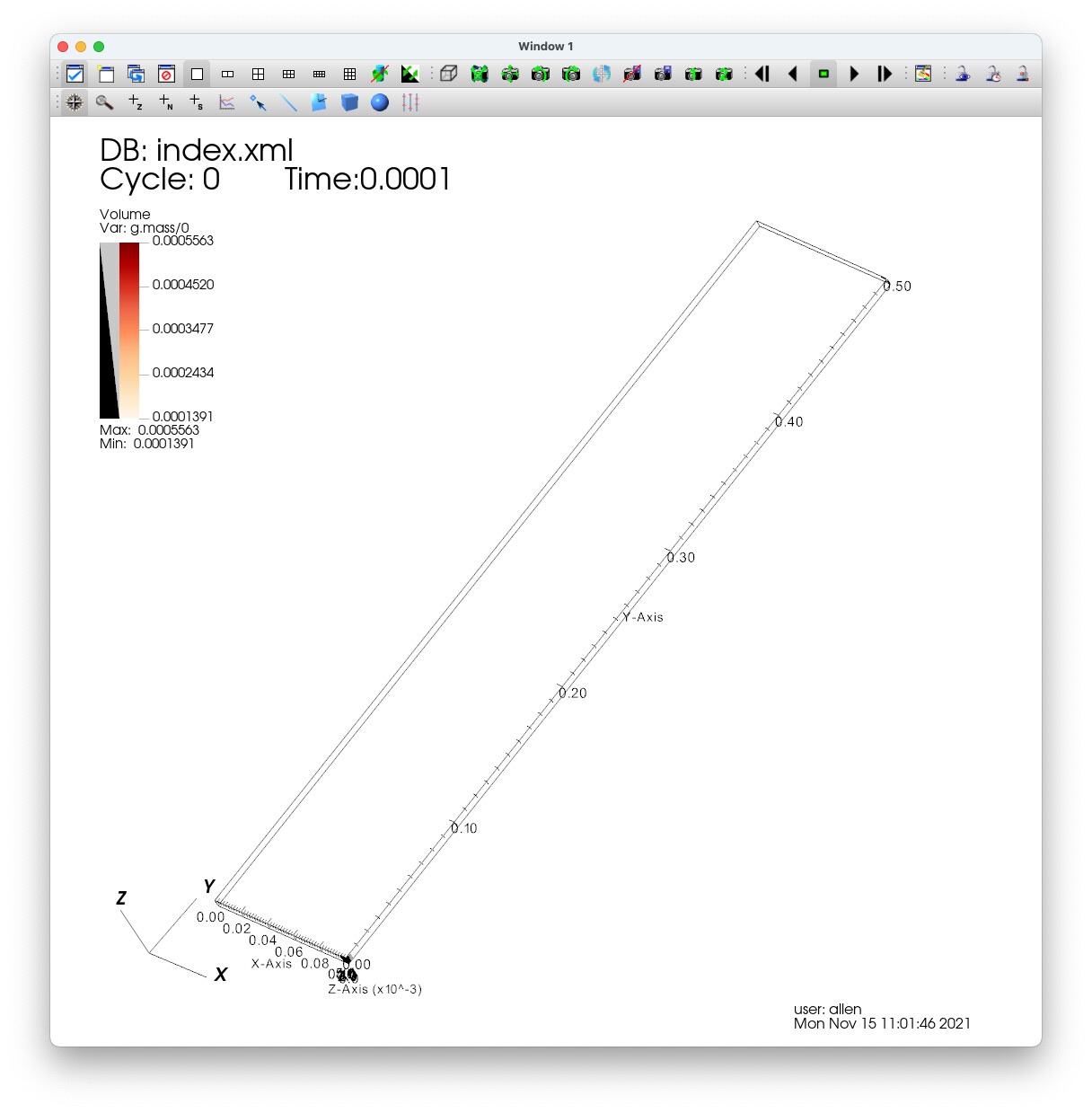
Then I tried to do the exact same rendering but with only a single scalar. I turned the IndependentComponents to on. That renders but the image is very vary faint. Absolutely nothing else in my pipeline changed yet the images are very different.
I have a similar pipeline that renders on screen. I can replicate the results. Two components is fine but one gives a faint image. I have tried some experiments to isolate the issue but can not.
The other issue I see with both is if I set the vtkVolumeProperty::SetShade to on, the rendered image turns gray. That is all of the resulting pixels are heavily shaded. I am thinking that perhaps these issues might be related.
Any insight from the community would be appreciated. Thank.
I would recommend not to use vtkSmartVolumeMapper because it just adds a layer between you and the actual mapper, so it is harder to figure out what actually happens. Volume rendering is complicated enough wothout this extra layer.
Maybe when you enable/disable independent components then the “smart” volume mapper decides to switch to another mapper without your knowledge. Or maybe it has a bug and in that mode the smart mapper does not set some parameter correctly.
Faint rendering is most often due to too large sampling distance, so play around with the different sampling distances.
If you attach a few images then we may be able to tell what is wrong and how to fix it.
Thanks Andras for the clues. A few more details that I figured out today:
If the opacity is set to 1 for the last 2 of 256 entries it almost renders with one component as I would expect. I say almost because the very low opacity areas are fully translucent.
Does not matter if clamping is on or off.
The sample spacing does not seem to change anything. I may not be setting the all of attributes. If there is a specific one let me know which one.
I tried the vtkFixedPointVolumeRayCastMapper but got a blank image. I just swapped it with the vtkSmartVolumeRenderer so probably did not have it set up correctly. If there is another mapper I should try let me konw
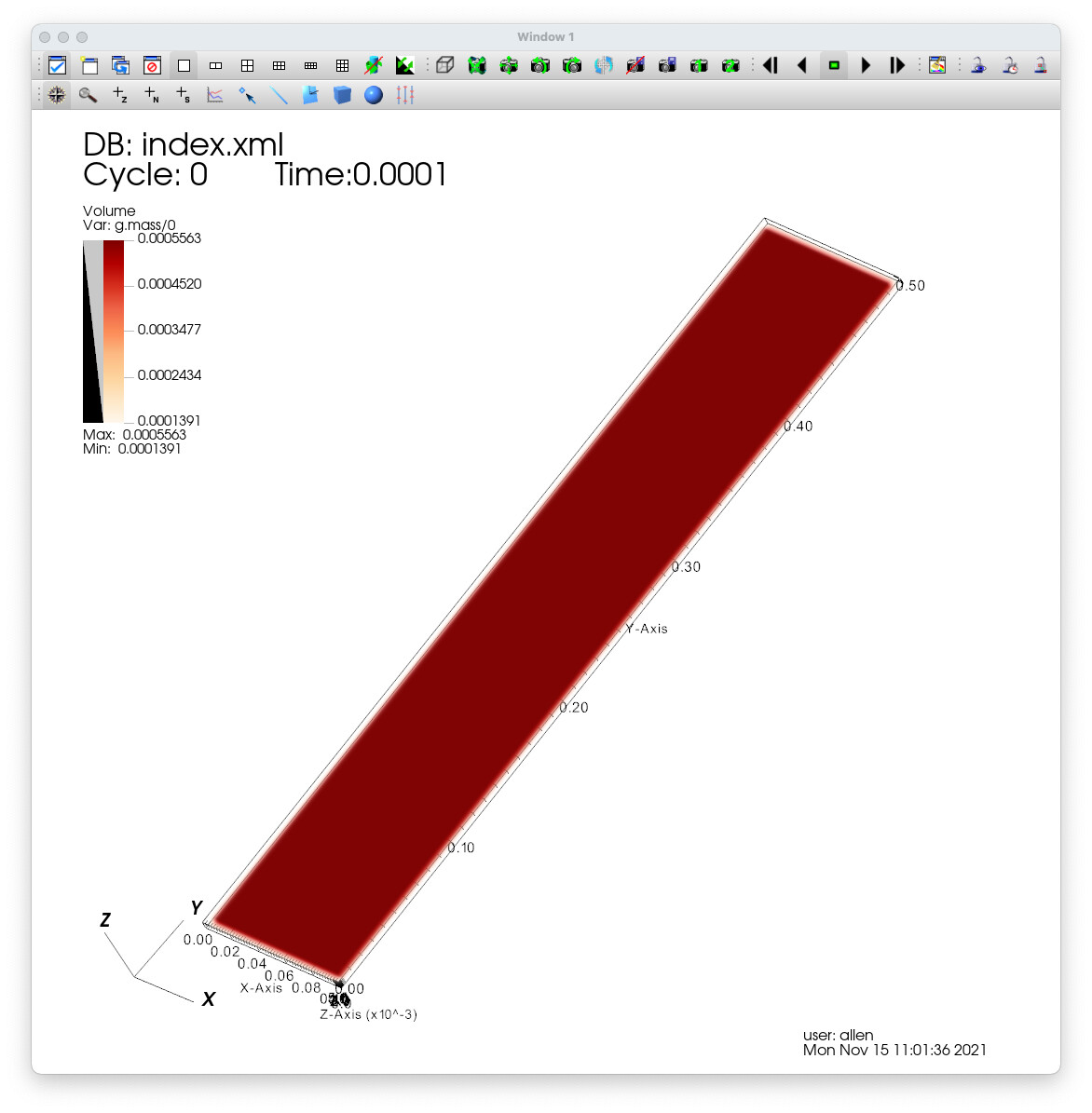
Some images all using the smart mapper:
Two components with the last two opacity values set to ~.99 (expected result)
Unless you are on a headless machine or your image size does not fit in your GPU memory then you probably want to use vtkGPUVolumeRayCastMapper.
Can you copy-paste here the xy points of your scalar opacity transfer function (or the code that generates it)?
The volume seems to be degenerate in the sense that it is almost 2-dimensional, which may make it not a good candidate for 3D volume rendering. What are the extent and spacing values of your vtkImageData? If it consists only of a handful of slices and the slices are very close to each other then rendering it using the old-school texture mapping approach (as a set of semi-transparent textured rectangles) might work better.
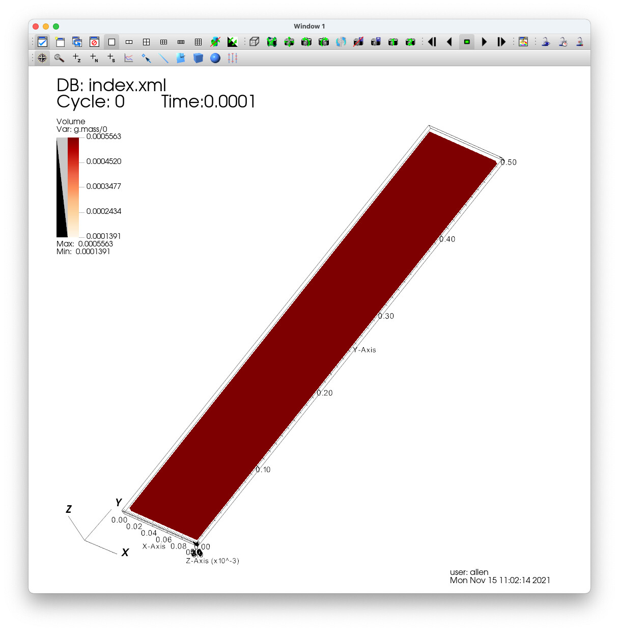
Another clue - the grid spacing is 0.000787402 but if I make it 100x greater 0.0787402 with everything equal including ramp opacity then I am seeing more of what I expect with two components.
As such, there seems to be a different sampling that is occurring with two components versus one as it relates to the opacity.
Your data set is very is hugely anisotropic (have 2 magnitudes difference in extents, bounds, and spacing) and and not normalized (having spacing 3 magnitudes away from unit spacing). All these can cause various estimations and heuristics to fail and you can easily run into to numerical precision issues.
For example, your current sampling distance (6.6e-3) is huge, about 10x larger than the spacing (7.8e-4), which means that you are lucky if you get a sample inside your 7-slice thin plane at all. You would need to reduce the sampling distance by a factor of 10, but if you want to avoid wood grain artifacts then potentially by a factor of 100 (or enable jittering).
If this increases rendering time too much then it might make sense to render the 7 slices as 7 textured planes instead of a volume.
On one level that makes perfect sense but only if the results were consistent across using one or two components. The fact the result vary so differently depending on whether there is one or two components is really the issue. I would expect the results to be consistent.
I have not looked at the VTK code but it would appear to me that two separate paths are be taken to determine the opacity. That does not seem correct.
Dependent and independent components may be two completely different processing inside the mapper. For example, one may use “interpolate first” compositing, while the other may use “classify first”, which are not equally impacted by sampling deficiencies. You can dump the generated GLSL shading code to the console and inspect it to get a definitive answer.
I tried another experiment using the vtkGPUVolumeRayCastMapper. I scaled my dataset by 100 in all directions. At this point the resulting images are the similar but not the same. The second component is a duplicate of the first component so I would expect the opacity mapping to be the same. But it is different. Here again, the results are not as expected.
As such, without dumping the GLSL code I am going to say there are two completely different processing paths, one of which suffers from sampling deficiencies.
There are many options that influence what exact processing path is taken (CPU/GPU volume rendering, depth peeling is enabled or not, if there are semi-transparent objects in the field of view, cropping enabled/disabled, jittering enabled/disabled, shading enabled/disabled, single-volume/multi-volume rendering is used, etc.). It is practically impossible to keep rendering results (or even features and limitations) consistent between all these options for several reasons.
For example, you spend $30k to get a new feature developed (or bug fixed) in one of these rendering paths. VTK maintainers will recognize that it is useful and they integrate it into VTK. They cannot demand that you to spend an additional $50k to add that feature or fix that issue in all the other processing paths “to be consistent”.
But even if infinite time and money could be spent on keeping all the volume rendering paths in VTK consistent, there can be inherent limitations in hardware or computational algorithms that makes 100% consistency practically impossible.
I agree but given that in this case the difference is “simply” where the lookup value comes from either component one or component two. I would not have expected different paths for that.
I just swapped to the OSPRay renderer and the results were slightly different in the actual rendering. I would expect some slight differences. But I also had to scale 1000 and there looks like a slight pixel shift. The spacing seems to be a key factor. The pixel shift not sure what to think but not too bothered by that.
Thanks for chiming in, greatly appreciated. Good fodder.