vtkWarpScalar produces hexagonal peaks

Hi,
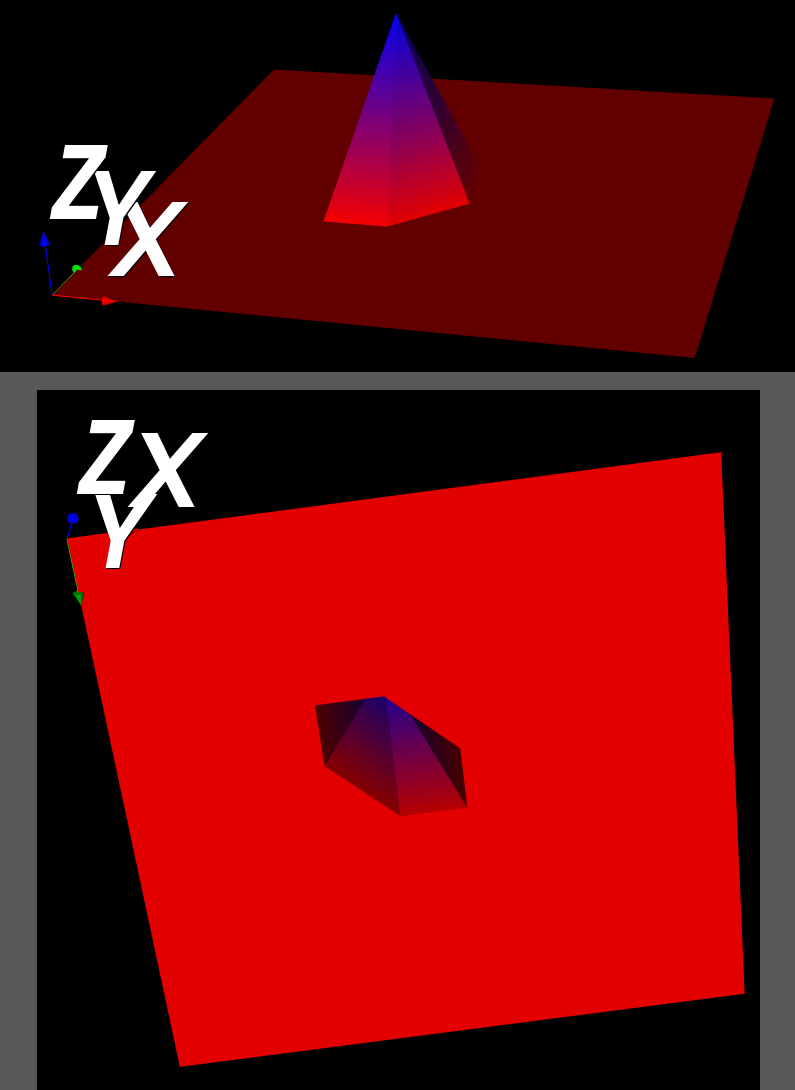
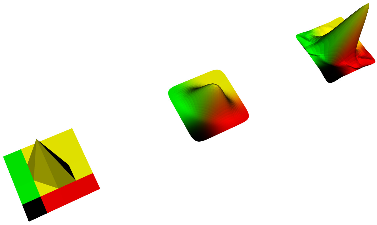
I am trying to create a simple height map from a numpy array. Everything is zero, except for a peak in the center. The peak is hexagonal, and tilted, and so it’s not symmetrical. I want to create a spectrogram, but hexagonal peaks are going to really skew the figure.

The code and resulting figure are given below. Help greatly appreciated. Please!

import numpy as np
import vtk

def main():

##############################
# 0. INITIALIZE
##############################
# data
imgImport = vtk.vtkImageImport()
imageData = vtk.vtkImageData() # data (image)

# processing (visualization pipline)
geometry = vtk.vtkImageDataGeometryFilter() # image->poly 
warp  = vtk.vtkWarpScalar() # filter
mapper  = vtk.vtkPolyDataMapper()  # mapper

# view (graphics pipeline)
actor_axes = vtk.vtkAxesActor() # actor: axes
actor = vtk.vtkActor() # actor: main
ren = vtk.vtkRenderer() # renderer
renWin = vtk.vtkRenderWindow() # window
iren  = vtk.vtkRenderWindowInteractor() # interactor

##############################
# I. INPUT
##############################
data_matrix = np.zeros([10,10], dtype=np.float32)
data_matrix[4,4] = 3
sz = data_matrix.shape
R, C = sz[0], sz[1]
       
imgImport.SetImportVoidPointer(data_matrix) # len(data_string)
imgImport.SetDataScalarTypeToFloat()
imgImport.SetDataExtent(0, C-1, 0, R-1, 0, 0)
imgImport.SetWholeExtent(0, C-1, 0, R-1, 0, 0)
imgImport.Update()
imageData = imgImport.GetOutput()

##############################
# II. PROCESS
##############################

##############################
# IIIa. VISUALIZATION PIPELINE
##############################
# Filter 1: image data to polydata
geometry.SetInputData(imageData)
geometry.Update()

# Filter 2: warp
warp.SetInputConnection(geometry.GetOutputPort())

# Mapper
mapper.SetInputConnection(warp.GetOutputPort())

##############################
# IIIb. RENDER PIPELINE
##############################
# 1/4. Actor
actor.SetMapper(mapper)

# 2/4. Renderer
ren.AddActor(actor_axes)
ren.AddActor(actor)
ren.ResetCamera()

# 3/4. Window
renWin.AddRenderer(ren)

# 4/4. Interactor
iren.SetRenderWindow(renWin)
iren.Initialize()
iren.SetInteractorStyle(vtk.vtkInteractorStyleTrackballCamera())    
iren.Start()

######################################
if name == ‘main’:
main()

If I understand correctly, this is a “resolution” effect due to the relative coarseness of the mesh. I assume that you are looking for a “smooth” peak. You might want to try something like vtkAdaptiveSubdivisionFilter or vtkButterflySubdivisionFilter. Alternatively / in conjunction with these filters, you might also try vtkWindowedSincPolyDataFilter to smooth the mesh.

Yes, I am looking for a ‘smooth’ peak. But more importantly, I am looking for something symmetric, even if it is coarse.

I will try the filters you mentioned, but I’m worried that a simple example like this gives a hexagonal base for the peak, rather than say a diamond shaped base.

Yes, as expected, the subdivision creates smoothing, but doesn’t solve the asymmetry problem. Here is the code, modified from https://vtk.org/Wiki/VTK/Examples/Python/PolyData/SubdivisionFilters to run on VTK 9, followed by the resultant image:

import vtk
import random
import numpy

Make a 32 x 32 grid

size = 5

Define z values for the topography (random height)

topography = numpy.zeros([size, size])
topography[2][2] = 5
‘’’
for i in range(size):
for j in range(size):
topography[i][j] = random.randrange(0, 5)
‘’’

Define points, triangles and colors

colors = vtk.vtkUnsignedCharArray()
colors.SetNumberOfComponents(3)
points = vtk.vtkPoints()
triangles = vtk.vtkCellArray()

Build the meshgrid manually

count = 0
for i in range(size-1):
for j in range(size-1):

    z1 = topography[i][j]
    z2 = topography[i][j+1]
    z3 = topography[i+1][j]
    
    # Triangle 1
    points.InsertNextPoint(i, j, z1)
    points.InsertNextPoint(i, (j+1), z2)
    points.InsertNextPoint((i+1), j, z3)
    
    triangle = vtk.vtkTriangle()
    triangle.GetPointIds().SetId(0, count)
    triangle.GetPointIds().SetId(1, count + 1)
    triangle.GetPointIds().SetId(2, count + 2)
    
    triangles.InsertNextCell(triangle)
    
    z1 = topography[i][j+1]
    z2 = topography[i+1][j+1]
    z3 = topography[i+1][j]
    
    # Triangle 2
    points.InsertNextPoint(i, (j+1), z1)
    points.InsertNextPoint((i+1), (j+1), z2)
    points.InsertNextPoint((i+1), j, z3)
    
    triangle = vtk.vtkTriangle()
    triangle.GetPointIds().SetId(0, count + 3)
    triangle.GetPointIds().SetId(1, count + 4)
    triangle.GetPointIds().SetId(2, count + 5)
    
    count += 6
    
    triangles.InsertNextCell(triangle)
    
    
    # Add some color
    
    r = [int(i*10/float(size)*255),int(j*10/float(size)*255),0]
    
    colors.InsertNextTuple(r)
    colors.InsertNextTuple(r)
    colors.InsertNextTuple(r)
    colors.InsertNextTuple(r)
    colors.InsertNextTuple(r)
    colors.InsertNextTuple(r)

Create a polydata object

trianglePolyData = vtk.vtkPolyData()

Add the geometry and topology to the polydata

trianglePolyData.SetPoints(points)
trianglePolyData.GetPointData().SetScalars(colors)
trianglePolyData.SetPolys(triangles)

Clean the polydata so that the edges are shared !

cleanPolyData = vtk.vtkCleanPolyData()
cleanPolyData.SetInputData(trianglePolyData)

Use a filter to smooth the data (will add triangles and smooth)

Use two different filters to show the difference

smooth_loop = vtk.vtkLoopSubdivisionFilter()
smooth_loop.SetNumberOfSubdivisions(3)
smooth_loop.SetInputConnection(cleanPolyData.GetOutputPort())
smooth_butterfly = vtk.vtkButterflySubdivisionFilter()
smooth_butterfly.SetNumberOfSubdivisions(3)
smooth_butterfly.SetInputConnection(cleanPolyData.GetOutputPort())

Create a mapper and actor for initial dataset

mapper = vtk.vtkPolyDataMapper()
mapper.SetInputData(trianglePolyData)
actor = vtk.vtkActor()
actor.SetMapper(mapper)

Create a mapper and actor for smoothed dataset (vtkLoopSubdivisionFilter)

mapper = vtk.vtkPolyDataMapper()
mapper.SetInputConnection(smooth_loop.GetOutputPort())
actor_loop = vtk.vtkActor()
actor_loop.SetMapper(mapper)
actor_loop.SetPosition(10, 0, 0)

Create a mapper and actor for smoothed dataset (vtkButterflySubdivisionFilter)

mapper = vtk.vtkPolyDataMapper()
mapper.SetInputConnection(smooth_butterfly.GetOutputPort())
actor_butterfly = vtk.vtkActor()
actor_butterfly.SetMapper(mapper)
actor_butterfly.SetPosition(20, 0, 0)

Visualise

renderer = vtk.vtkRenderer()
renderWindow = vtk.vtkRenderWindow()
renderWindow.AddRenderer(renderer)
renderWindowInteractor = vtk.vtkRenderWindowInteractor()
renderWindowInteractor.SetRenderWindow(renderWindow)

Add actors and render

renderer.AddActor(actor)
renderer.AddActor(actor_loop)
renderer.AddActor(actor_butterfly)

renderer.SetBackground(1, 1, 1) # Background color white
renderWindow.SetSize(800, 800)
renderWindow.Render()
renderWindowInteractor.SetInteractorStyle(vtk.vtkInteractorStyleTrackballCamera())
renderWindowInteractor.Start()

Is there any way you can increase the underlying grid resolution?

Also, triangulating the underlying data so that edge incidence to a point is everywhere symmetric might help.

Yes, it looks like this is a known problem. This thread, I believe also addresses the same point. What do you think?

https://discourse.paraview.org/t/unsymmetric-contour-rendered-by-symmetric-data/4118/18

It’s a data resolution problem. The solution is to refine the mesh, as indicated in the thread. And BTW, in the thread, adding new points into the middle of a quad does not guarantee the correct solution since the interpolation function is just an approximation - it just looks better. This is a common problem in any discretized domain - without additional information, any interpolation in between points is subject to error.

Ok. I have 2D image data, a pandas dataframe, that I read using vtkImageDataGeometry filter. I then warp the values to get a height map. I will resample, and get back if I have problems, or have a question, or will post the solution. Thanks for the help.